28
Getting Started
STEP 3. Install the Network Analyzer Modules
• High Sensitivity measurement
• High Gain measurement
b.
below shows the
cable connection for standard Configurable Test Set measurement
configuration with M9378A and M9378B. This is the connection in both
situations, where coupler M9378A/B is to the left side of the M9377A
and where M9378A/B is on the right side of the M9377A.
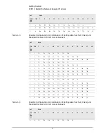
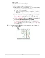
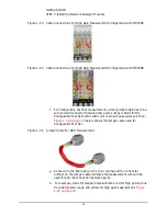
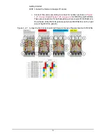
Figure 1-18 Cable Connections For Standard Measurement Configuration with M9378A
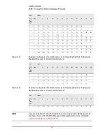
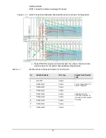
Figure 1-19 Cable Connections For Standard Measurement Configuration with M9378B
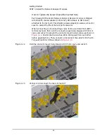
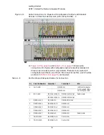
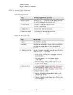
c.
below shows the
cable connection for high power measurement with M9378A and
M9378B. Its important to ensure that test port labeled 6 (ATT Out) is
connected to test port 4 (Thru R). Similarly, connect test port 7 (ATT In)
to test port 5 (Thru T). This connection ensures that the current flows
through high power 20 dB attenuator.
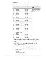
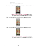
Figure 1-20 Cable Connections For High Power Measurement Configuration with M9378A


