27
Getting Started
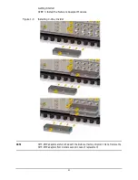
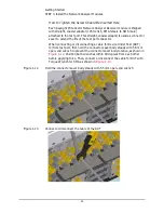
STEP 3. Install the Network Analyzer Modules
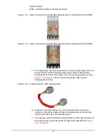
* A SMB-SMA adapter is required to connect this cables with M9340A.
Attach the SMB-SMA adapter to the M9340A before installing into the
chassis.
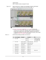
** When the system rack is used, 1U space should be placed between
Chassis 1 and 2. In such cases M9485-61633, M9485-61634 and
M9485-61635 are used instead.
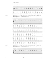
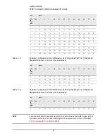
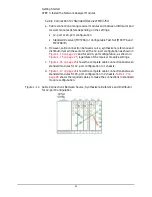
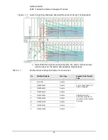
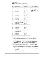
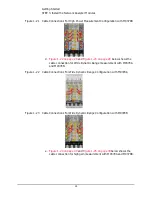
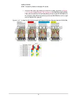
Cable Connection for Configurable Test Set, M9377A & M9378A/B
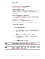
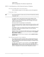
a. With the Configurable Test Set, the cable connection within the Direct
Access Receiver and Directional Coupler modules defers depending on
the test purpose:
• Standard
• High Power measurement
11
M9485-61611
Semi rigid
Socket and torque driver (to
be used with socket
adapter), set to 8 in-lb (not
supplied)
12
M9485-61612
Semi rigid
13
M9485-61613
Semi rigid
14
M9485-61614
Semi rigid
15
M9485-61615
Semi rigid
16
M9485-61616
Semi rigid
17
M9485-61617
Semi rigid
18
M9485-61618
Semi rigid
19
M9485-61619
Semi rigid
21
M9485-61633 (For system rack)
M9485-61621 (For 2 tier chassis)
Semi rigid
22
M9485-61622
Semi rigid
23
M9485-61634 (For system rack)
M9485-61623 (For 2 tier chassis)
Semi rigid
24
M9485-61624
Semi rigid
25
M9485-61625
Semi rigid
26
M9485-61635 (For system rack)
M9485-61626 (For 2 tier
chassis)**
Semi rigid
27
M9485-61627
Semi rigid
28
M9485-61628
Semi rigid
29
M9485-61629
Semi rigid
No
Cable Part Numbers
Cable Type
Required Tool to Place the
Cable


