


8
Installation Note E6650-90013
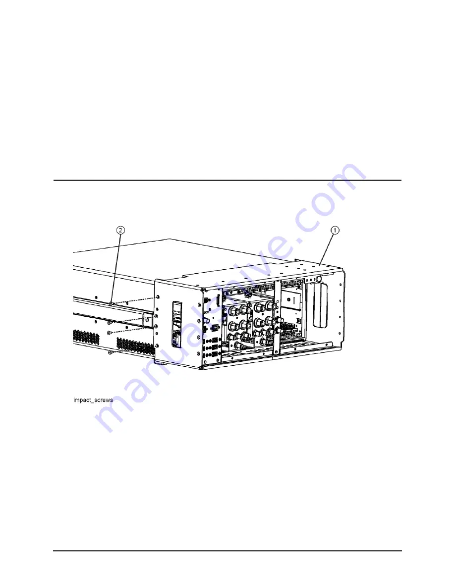
Installation Procedure
5.
. Remove the 4 screws
(2)
on each side of the Impact cover
(1)
. This will
disconnect it from the chassis frame. Slide the Impact cover away from the chassis and over
the Controller and Reference panels which were disconnected in the previous step.
NOTE
The Controller panel cover panel and Reference panel do not need to be
removed with the Impact cover. The Controller panel and the Reference panel
may be tilted in and the Impact cover slipped around them.
Removal of the Impact cover over the Controller panel requires you to move
the Impact cover towards the controller. This will allow you to tilt the
Controller sub-panel. See
Figure 4
Impact Cover Screws


