


58
59
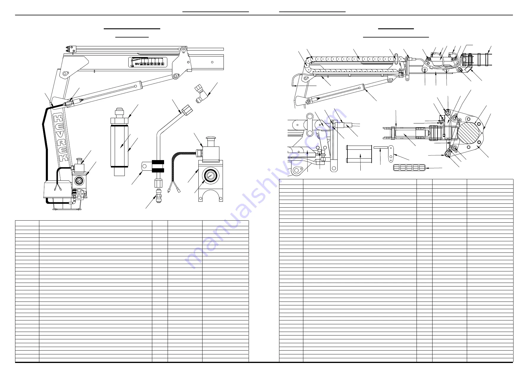
Load Indicators
All Models
Item No.
Description
QTY
Notes
Order Part No.
1
550 Load Indicator Kit Complete
1
1000/30/550
2
700 Load Indicator Kit Complete
1
1000/30/700
3
1000 Load Indicator Kit Complete
1
1000/30/1000
4
1500 Load Indicator Kit Complete
1
1000/30/1500
5
Load Indicator Gauge – 550
1
1000/30/10
6
Load Indicator Gauge – 700
1
1000/30/11
7
Load Indicator Gauge – 1000
1
1000/30/12
8
Load Indicator Gauge – 1500
1
1000/30/13
9
Load Indicator Gauge – Specify
1
Specify
1000/30/??
10
Load Indicator – Emergency Stop Housing
1
1000/30/15
11
Emergency Stop Kit Complete
1
1000/1/31
12
Load Indicator – Attachment Pipe
1
1000/30/15/C
13
Adapter – M/F 7/16
1
1000/22/18
14
Adapter – M/M 7/16 JIC
1
1000/30/15/E
15
Pipe Clamp
1
1000/30/15/D
16
Hose Burst Velocity Fuse
1
1000/30/14
17
Velocity Fuse Holder
1
1000/30/14/A
18
Adapter
1
1000/2/5
19
Load Indicator Hose (Lift Cylinder Hose)
1
1000/16/1
20
Velocity Fuse Complete
1
1000/30/14/B
PARTS BREAKDOWN
Pole Grab
K1000/K1500 Series
Item No.
Description
QTY
Notes
Order Part No.
1
Pole Grab Assembly – Complete
1
1000/40/1
2
Hose Chain Tray – Steel
1
1000/40/2
3
Hose Chain Links (16p/m 35 per Crane)
35
1000/40/3
4
Hose Chain Track Dividers – Inside Chain
12
1000/40/4
5
One Piece Steel End – Male – 3rd Boom
1
1000/40/5
6
One Piece Steel End – Female – Steel Tray
1
1000/40/5/A
7
Lift Cylinder – Stainless Steel Rod
1
1000/40/6
8
Tilt Cylinder
1
1000/40/7
9
Clamp Cylinder
1
1000/40/8
10
Grab Attachment Arm
1
1000/40/9
11
Tilt Body
1
1000/40/10
12
Claws
2
1000/40/11
13
Tilt Cylinder Attachment Pin – Piston End
1
1000/40/12
14
Tilt Cylinder Attachment Pin – Gland End
1
1000/40/13
15
Tilt Body Attachment Pin
1
1000/40/14
16
Claw to Tilt Body Retaining Pin
2
1000/40/15
17
Clamp Cylinder Retaining Pins – Claws
2
1000/40/16
18
Tie Rod
1
1000/40/17
19
Tie Rods Ends – M12
2
1000/40/18
20
Bulkhead Fitting 90 degree Chain Tray End
4
1000/40/19
21
Bulkhead Fitting Straight ¼ BSPP 3rd Boom
2
1000/40/20
22
Bulkhead Fitting Straight 3/8 BSPP 3rd Boom
2
1000/40/21
23
Breakaway Coupling ¼ Male – Near Side
2
1000/40/22
24
Breakaway Coupling ¼ Female –Far Side
2
1000/40/22/A
25
Breakaway Coupling 3/8 Male – Far Side
2
1000/40/23
26
Breakaway Coupling 3/8 Female – Far Side
2
1000/40/23/A
27
Steel Tracking Guide
1
1000/40/24
28
Hose – DCV to Chain Tray
4
1000/40/25
29
Hose – Bulkhead Tray to Bulkhead 3rd Boom
4
Inside
1000/40/26
30
Hose – Bulkhead 3rd Boom to Clamp & Tilt Cylinder
4
1000/40/27
31
Bulkhead Mount Plate
1
1000/40/28
32
Control Valve Decal
1
1000/40/29
33
Pin Retaining Grub Screws
6
1000/40/30
34
Plastic Dust Cap to Suit ¼ B/A Male
2
Not Pictured
1000/40/31
35
Plastic Dust Cap to Suit ¼ B/A Female
2
Not Pictured
1000/40/31/A
36
Plastic Dust Cap to Suit 3/8 B/A Male
2
Not Pictured
1000/40/32
37
Plastic Dust Cap to Suit B/A Female
2
Not Pictured
1000/40/32/A
38
Clamp Cylinder Fitting
1
1000/8/9
39
Clamp Cylinder Fitting 90 degree
1
1000/8/10
40
Tilt Cylinder Fittings
2
1000/2/5
41
7/16 UNO Plug
2
Not Pictured
1000/8/11
42
Boom Locking Pin
4
1000/6/2
43
Hook Storage Teardrop
1
1000/20/22
44
Hook Storage Joiner Bar
1
1000/20/23
45
Load Holding Valve – Clamp Cylinder
1
1000/8/4
46
Bearing Cylinders all Pivot Points
12
No Pictured
1000/20/11/A
47
Control Valve
– see page 26
1
1000/2/19
LOAD INDICATOR
10
9
11
14
15
18
17
16
11
19
20
13
12
13
10
MINIMUM POLE DIAMETER
Ø175.0mm
TILT
CLAMP
SLEW
BOOM
TELESCOPE
UP
DOWN
OPEN
CLOSE
LEFT
RIGHT
EXTEND
RETRACT
LOWER
RAISE
3
4
29
27
31
13
40
8 30 14
30
12
30
46
9
28
2
7
5
21 23+24
22
25+26
6
20
27
44
43
32
8
10
45
39
38
18
19
16
12
12
42
42
15
11
17
16
17
33
10
PARTS BREAKDOWN