background image

21

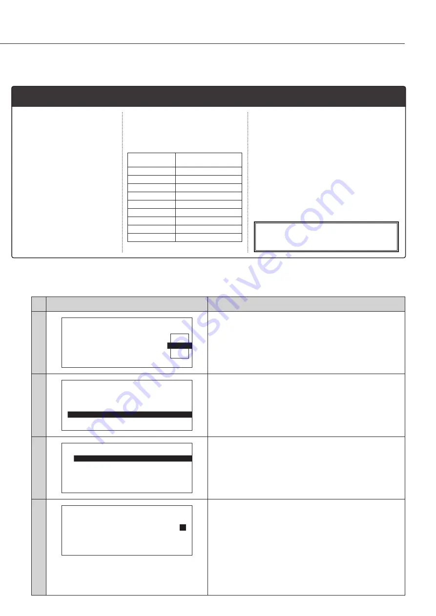
■ Setting the channel parameter

Following four items can be set per channel.

*  To cancel the setting during operation, press the [EXIT] key. Then, the previous screen will be restored.

Step

Display

Operation

1 . C H

P A R A M E T E R

0 1

F L O U R

C H

N A M E

S M O O T H I N G

M E A S

N T

1

C O M P .

P A R A M E T E R

2

C A N C E L

●  Enter the averaging times in the normal measurement.

Select the averaging times (01 to 16) using

 [

]/[

key, and press 

the [ENTER] key to set.

1 . C H

P A R A M E T E R

0 1

F L O U R

C H

N A M E

F L O U R

S M O O T H I N G

1

M E A S

N T

1

C O M P .

P A R A M E T E R

O K

C A N C E L

●  Set the composition parameter.

Move the cursor to [COMP. PAR AMETER] using [

]/[

] key. 

Then, press the [ENTER] key to set.

1 . 0 1 . F L O U R

C O M P .

P A R A M E T E R

1

M O I S T U R E

2

P R O T E I N

3

C O M P 3

4

C O M P 4

E X I T

●  Select a composition parameter.

Move the cursor to the desired composition with [

]/[

] key. 

Then, press the [ENTER] key to select.

1 . 0 1 . F L O U R

C O M P .

P A R A M E T E R

1

M O I S T U R E

N A M E

M O I S T U R E

D I G I T

* * * *

.

D I S P L A Y

O N

a 0

1 0 . 6 5 9 9

a 1

4 9 . 1 6 3 4

●  Set the composition name.

If already entered, move the cursor to the right end [

], and 

press the [ENTER] key. The composition name will be set.

<To enter or edit>

  Move the cursor using the [EXIT] and [ENTER] keys.

  Input the composition name from the 1st character using the 

numeric keypad and  move the cursor one by one with the 

[Enter] key. Up to 8 characters can be entered. After input is 

done, move the cursor to the right end [

] using the [ENTER] 

key. Then, press the [ENTER] key again to set.

1

 Composition name 

  (8 alphanumerics)

  A composition identification.

  It will be displayed when 

displaying the measurement 

value.

4. Composition parameter (Following five items can be set per composition)

 step (8)

 step (9)

2

 Measurement value display digits

  The display range changes 

according to the display digits 

setting.

Number of 

display digits

Display range

***.*

0.0 

 999.9

**.*

0.0 

 99.9

***.**

0.00 

 999.99

**.**

0.00 

 99.99

**.***

0.000 

 99.999

*.***

0.000 

 9.999

*.****

0.0000 

 9.9999

*****

 99999

****.*

0.0 

 9999.9

3

 Display setting (→ Step (10))

  Sets the display or hide of the composition.

4

 Coefficient (→ Step (11))

  A coefficient of the formula (calibration 

cur ve) to calculate composition from 

absorbance.

5

 Correction parameter (→ Step (12) (13))

  Setting offset value and tilt correction value 

will enable correction of measurement 

value.

Composition value (displayed composition) after 

correction = Composition value before correction x 

Tilt correction value + Offset value

Summary of Contents for KB-270

Page 1: ...NIR Composition Analyzer KB 270 Operating Manual Thank you for purchasing this product Please read the operating manual carefully and use this product properly...

Page 2: ......

Page 3: ...3 7 Making the calibration curve 14 7 1 Setting the measurement range and the number of samples 14 7 2 Setting the sampling times 14 7 3 Preparing the samples 14 7 4 Moisture preparation 15 7 5 Measur...

Page 4: ...dor Do not allow the unit to come in contact with water This unit is not waterproof Do not allow water or other liquids to get into the unit s enclosure as this may lead to electric shock or malfuncti...

Page 5: ...t sunlight electromagnetic interference corrosive gases or large amounts of dust Place the unit on a flat and stable surface where it will not be subjected to significant vibration during use When mov...

Page 6: ...composition measurements It measures the near infrared absorption of six wavelengths of the measuring object and converts the obtained data to the composition The multiple compositions four compositi...

Page 7: ...ual this document PC software USB cable VZC61 Using the supplied PC software various operations such as zero adjustment measurement setting the calibration curve device setting and maintenance can be...

Page 8: ...content Channel number Channel name Composition Absorbance Operating temperature range 5 to 35 C no condensation Power supply 100 120 V AC 220 240 V AC 50 60 Hz Power Consumption 50W Dimensions and w...

Page 9: ...A key Used for measurement TABLE key Used to set ON OFF of the rotation table ZERO key Used for zero adjustment EXIT key Used to exit the operation MODE key Used to select the measurement mode CH key...

Page 10: ...justment will proceed while displaying the absorbance in real time When the calibration is completed the initial screen will be restored If the power is cycled repeat the operation from step 6 Make su...

Page 11: ...surement error tends to occur depending on the light absorption characteristics of the plastic bag 3 Polyethylene sheet only for moisture Rice ball boiled noodle and uncooked noodles etc For large sol...

Page 12: ...n When rotating the table using a 90 mm of Petri dish use the sample cell holder Also use the light shielding cover to prevent falling off When using the polyethylene sheet prevent the sheet from bein...

Page 13: ...e saturated sampling amount If the sampling amount is sufficiently prepared set the sampling amount more than the absorbance saturated sampling amount Refer to P 30 Remarks if the absorbance saturated...

Page 14: ...This is called calibration curve The calibration curve differs depending on the measuring object Therefore it is required to make calibration curve per object in advance This unit is capable of makin...

Page 15: ...the obtained data as the standard composition As the over drying method the official method or a measurement using an infrared moisture analyzer is available Note that the sample cannot be reused in...

Page 16: ...ing 1234 Present ON 1 2 3 4 Present OFF Absent Setting not available When changing the measurement channel the channel that has no coefficient or the one whose display setting of all four compositions...

Page 17: ...7 6 X 3 0 5 1 5 4 X 4 0 4 1 8 1 X 5 0 1 9 8 4 X 6 0 1 2 9 6 Set the sample to cover up the measurement window The continuously measured absorbance will be displayed Set the smoothing value as require...

Page 18: ...he light shielding cover and set the zero adjustment plate onto the rotation table of the unit Then close the cover Perform zero adjustment Press the ZERO key The zero adjustment screen will be displa...

Page 19: ...essing the ENTER key will enable the setting Set the item referring to the corresponding pages Display Contents Page 1 C H P A R A M E T E R Setting the channel parameter P 20 2 C H D U P L I C A T E...

Page 20: ...A S N T 2 C O M P P A R A M E T E R C A N C E L Enter the smoothing value of continuous measurement Select the smoothing value 0 to 5 using key and press the ENTER key to set A channel identification...

Page 21: ...set To enter or edit Move the cursor using the EXIT and ENTER keys Input the composition name from the 1st character using the numeric keypad and move the cursor one by one with the Enter key Up to 8...

Page 22: ...N C E L Enter the offset value To correct enter the value in the same procedure as step 11 Enter 0 if correction is not needed 1 0 1 F L O U R C O M P P A R A M E T E R 1 M O I S T U R E O F F S E T...

Page 23: ...uplication destination channel Move the cursor to the destination of channel duplication with key and press the ENTER key to set Press the ENTER key when the confirmation screen is displayed The menu...

Page 24: ...0 2 F L O U R 2 12 3 4 0 3 C O R N 1 12 4 0 4 C O R N 2 1 0 5 B U T T E R 1 2 3 0 6 F L O U R 1234 0 7 Select the channel to initialize Move the cursor to the channel to initialize with key Then press...

Page 25: ...M is selected Select USB or LAN using key and press the ENTER key to set 4 C O M S E T T I N G C O M U S B X P O R T O K C A N C E L 4 C O M S E T T I N G M A C A D D R E S S I P A D D R E S S O K Che...

Page 26: ...5 P A S S C O D E N E W C O D E 1 2 3 4 Set the pass code After four digits are input the cursor will move to the right end automatically Pressing the ENTER key will restore the menu screen after savi...

Page 27: ...d off Be careful of the edges inside the main unit Otherwise it may cause an injury etc 11 Maintenance Step Operation Rear of the main unit Turn off the power and disconnect the power cable The lamp h...

Page 28: ...11 3 Consumable parts To use the unit in the best accuracy it is recommended to replace consumable parts at an interval of two years Other than the light source lamp do not replace the consumable part...

Page 29: ...k the ambient temperature E 05 Sample low reflection The reflectivity of sample is low and the signal level is below the requirement When sample is not set on the measurement window Set the sample and...

Page 30: ...absorbance saturated sampling amount While the near infrared from the bottom passes through the sample the displayed value will continue to fluctuate If the following is met making calibration curve...

Page 31: ...31...

Page 32: ...rts depicted in this user manual may not appear exactly as their actual counterparts but this does not affect their operation or functionality This user manual was intended to be written as clearly an...

Reviews: