


TK-782
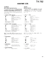
ADJUSTMENT
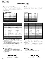
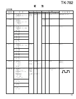
Adjustment Location
■
Switch
MODULAR
MIC JACK
CALL
CALL
DC
SOURCE
BUSY/
TX LED
VOLUME
UP
VOLUME
DOWN
CHANNEL UP
CHANNWL DOWN
SUB
DISPLAY
MONITOR
PRIORITY
SERVICE
AUXILIAY
HANDSET
SCAN
PROGRAMMABLE
FUNCTION KEYS
ALPHANUMERIC
DISPLAY
■
Adjustment Point
■
Note
• Flash memory
The firmware program (User mode, Test mode, Tuning
mode, etc.) and the data programmed by the FPU (KPG-77D)
for the flash memory, is stored in memory. When parts are
changed, program the data again.
• EEPROM
The tuning data (Deviation, Squelch, etc.) for the
EEPROM, is stored in memory. When parts are changed,
readjust the transceiver.
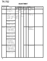
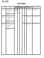
Measurement
Test-
equipment
Unit
Terminal
Adjustment
Unit
Parts
Method
Specifications/Remarks
Condition
Item
1. PLL lock
1) Set test mode
DVM
TX-RX
TP1
PLL
TC101 1.5V (Receive)
±
0.1V
voltage
CH : CH3 - Sig1
Power meter (A/2)
PTT : OFF (Receive)
TC102 1.5V (Transmit)
PTT : ON (Transmit)
2) CH : CH2 - Sig1
Check
8.0V or less
PTT : OFF (Receive)
PTT : ON (Transmit)
Common Section
■
Repair Jig (Chassis)
Use jig (Part No. : A10-4010-02) for repairing the TK-782.
The jig facilitates the voltage check when the voltage on the
component side TX-RX unit (A/2) is checked during repairs.
L203
L204
L202
L6
VR1
TX-RX UNIT (A/2)
PLL/VCO
TC101
TP1
TC102
64
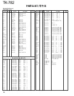
Summary of Contents for TK-782
Page 64: ...TK 782 1 8 1 BLC 2 PSB 3 E 4 PTT 5 ME 6 MIC 7 HOOK 8 CM 63 ...
Page 68: ...TK 782 67 ...
Page 70: ...TK 782 69 ...
Page 72: ...TK 782 71 ...
Page 74: ...TK 782 73 ...
Page 76: ...TK 782 75 ...
Page 78: ...TK 782 77 ...