


35
TK-782
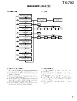
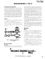
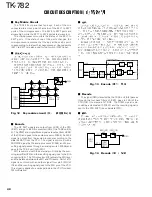
Frequency Configuration
The TX-RX unit (A/2) incorporates a VCO, based on a frac-
tional N type PLL synthesizer system, that allows a channel
step of 12.5kHz to be selected. The incoming signal from
the antenna is mixed with a first local oscillation frequency
to produce a first intermediate frequency of 44.85MHz.
The signal is then mixed with a second local oscillation
frequency of 44.395MHz to produce a second intermediate
frequency of 455kHz. This is called a double-conversion sys-
tem. The TX-RX unit (A/2) contains a wide/narrow MCF and
CFs. The transmit signal is produced by the PLL circuit for
direction oscillation and division. The signal output from the
VCO is amplified by a straight amplifier and transmitted.
ANT
SW
RX
AMP
1st
MIX
TX
AMP
POWER
AMP
CF 455kHz
(Wide)
CF 455kHz
(Narrow)
MCF
44.85MHz
+
MIX/IF/DET
175.15~
190.15MHz
PLL/VCO
VCXO
16.8MHz
220~235MHz
220~235MHz
44.395MHz
AFO
MD
MB
Fig. 1 Frequency configuration
"
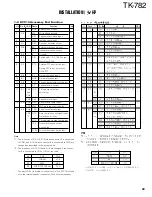
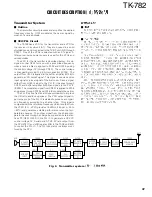
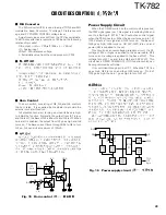
CIRCUIT DESCRIPTION /
LPF
ANT
HPF
L202~204
BPF
Q202
AMP
Q15
AMP
IC2
AMP
IC202
MIX
XF1
BPF
D211,212
ANT
SW
+
CF1/
CF2
IC11
MIX,IF,DET
X2
2nd
local OSC
1st local
OSC (HT)
DEO
Fig. 2 Receiver system /
Receiver System
"
Outline
The incoming signal from the antenna passes through a
low-pass filter and a transmission/reception selection diode
switch (D211,D212) and goes to the front end of the receiver.
The front-end filter is a variable BPF consisting of three coils
and three varicap diodes (D206, D207, D208) to eliminate
unwanted out-of-band signal components. The low-noise
amplifier (LNA) (Q202) uses a bipolar transistor to achieve
wide-band and low-distortion amplification.
The signal passes through the BPF and is down-converted
with the first local signal by IC202 to produce the first IF sig-
nal of 44.85 MHz. The first local signal passes through an
LPF and an attenuator to eliminate unwanted harmonics com-
ponents and implement the optimum input level to the mixer,
then enters IC202. A DBM is used as a mixer to achieve a
high potential.
The signal output from the mixer passes through two
MCFs (XF1). The signal is amplified by an intermediate fre-
quency amplifier and input to the FM IF IC (IC11).
The first intermediate frequency signal is mixed with the
second local signal of 44.395MHz to produce the second IF
signal of 455kHz.
The unwanted near-by signal components are then elimi-
nated by a wide ceramic filter (CF1) or a narrow ceramic filter
(CF2) and the resulting signal goes back to the FM IF IC. The
signal is quadrature-detected in the IC to produce an audio
signal, which is amplified by a DET amplifier (IC2) and output
to the TX-RX unit (B/2).
Summary of Contents for TK-782
Page 64: ...TK 782 1 8 1 BLC 2 PSB 3 E 4 PTT 5 ME 6 MIC 7 HOOK 8 CM 63 ...
Page 68: ...TK 782 67 ...
Page 70: ...TK 782 69 ...
Page 72: ...TK 782 71 ...
Page 74: ...TK 782 73 ...
Page 76: ...TK 782 75 ...
Page 78: ...TK 782 77 ...