18
Chapter 1: Connection of Equipment
Chapter 1
Chapter 2
Chapter 3
Chapter 4
Chapter 5
Chapter 6
Chapter 7
Chapter 8
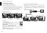
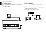
1-7 Daisy Chain Connection
1-7-2
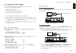
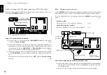
Connection of Video Output Terminals
Example Using S-VIDEO Connection
1
2
2
1
DIGITAL
DVD
CONTROL
CONTROL
MAIN
M A I N - S U B
S W I T C H
SUB2
SUB1
COAXIAL
I N
O U T
O U T
INPUT OUTPUT
D A I S Y C H A I N
S VIDEO
VIDEO
OUTPUT
I N P U T
O U T P U T
M I X L I N E
OPTICAL
(PCM/BIT STREAM)
INTERLACE
PROGRESSIVE
COMPONENT
VIDEO
OUTPUT
1
2
2
1
DIGITAL
DVD
CONTROL
CONTROL
MAIN
M A I N - S U B
S W I T C H
SUB2
SUB1
COAXIAL
I N
O U T
O U T
INPUT OUTPUT
D A I S Y C H A I N
S VIDEO
VIDEO
OUTPUT
I N P U T
O U T P U T
M I X L I N E
OPTICAL
(PCM/BIT STREAM)
INTERLACE
PROGRESSIVE
COMPONENT
VIDEO
OUTPUT
1
2
2
1
OUTPUT
S VIDEO
VIDEO
OUTPUT
I N P U T
O U T P U T
L I N E
INTERLACE
PROGRESSIVE
COMPONENT
VIDEO
OUTPUT
VIDEO
IN
Illust Model : DV-5900M
S-video cable (Provided)
MAIN
SUB 2
SUB 1
S-video cable (Provided)
S-video cable (Provided)
1-7-1
Setup
CONTROL
MAIN
M A I N - S U B
S W I T C H
SUB2
SUB1
D A I S Y C H A I N
Daisy Chain Connection
Up to three changer units can be connected in series.
÷
The three units can mutually control other units.
÷
Up to 1200 discs can be played back continuously by connecting three units.
÷
Relay playback, with which discs are played in a random order is possible.
Relay playback cannot control discs in the PLUS1 to PLUS3 slots.
Random relay playback cannot play discs in the PLUS1 to PLUS3 slots.
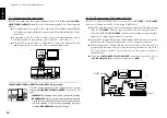
Set the
MAIN-SUB SWITCH
on the rear panel of each changer unit to a
different position from other changer units.
Be sure to unplug the power cord before changing the position of the
MAIN-SUB SWITCH
.
Be sure to set one of the
MAIN-SUB SWITCH
to “
MAIN
”.
It is the unit set as the “
MAIN
” unit that manages the discs and output the playback
signals to speakers.
When peripheral equipment (TV, AV amp, etc.) is used, connect it to the unit set as
the “
MAIN
” unit. “
Daisy Chain Function
”
W
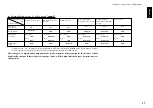
Connect the video output using either the S-VIDEO or COMPONENT VIDEO
connection.
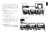
For the connection, connect the “
SUB2
” unit output to the “
SUB1
” unit input, then
connect the
“SUB1”
unit output to the “
MAIN
” unit input as shown in the figure
below.
1
2
2
1
L
R
DIGITAL
DVD
CONTROL
CONTROL
MAIN
M A I N - S U B
S W I T C H
SUB2
SUB1
COAXIAL
I N
O U T
O U T
INPUT OUTPUT
FRONT
SURROUND
CENTER
SUB WOOFER
D A I S Y C H A I N
A U D I O
C O M P O N E N T V I D E O
S VIDEO
VIDEO
OUTPUT
6 C H . I N P U T
I N P U T
I N P U T
Y
C b
C r
Y
C b
C r
O U T P U T
O U T P U T
M I X L I N E
OPTICAL
(PCM/BIT STREAM)
INTERLACE
PROGRESSIVE
COMPONENT
VIDEO
OUTPUT
L
R
DIGITAL
DVD
CONTROL
CONTROL
MAIN
M A I N - S U B
S W I T C H
SUB2
SUB1
COAXIAL
I N
O U T
O U T
INPUT OUTPUT
FRONT
SURROUND
CENTER
SUB WOOFER
D A I S Y C H A I N
A U D I O
C O M P O N E N T V I D E O
6 C H . I N P U T
I N P U T
I N P U T
Y
C b
C r
Y
C b
C r
O U T P U T
M I X L I N E
OPTICAL
(PCM/BIT STREAM)
DIGITAL
DVD
CONTROL
CONTROL
MAIN
M A I N - S U B
S W I T C H
SUB2
SUB1
COAXIAL
I N
O U T
O U T
INPUT OUTPUT
FR
D A I S Y C H A I N
M I X L I N E
OPTICAL
(PCM/BIT STREAM)
System control cable
(Provided)
System control cable
(Provided)
MAIN
SUB 2
SUB 1

