background image

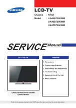
The PICTURE button on the Remote Control selects the modes for picture adjustment.

Press the PICTURE button on the Remote Control

Press the PICTURE button repeatedly to select the desired item for adjustment.
Each time it is pressed, the magenta-colored portion shifts in the order shown below to show that
the colored item in the list can be adjusted.

(1)  CONTRAST adjustment  mode

(2) BRIGHT adjustment  mode

(3) SHARP adjustment  mode

(4) COLOR adjustment  mode

(6)  NO  DISPLAY

(5) TINT  adjustment  mode

After selecting the desired mode, press VOLUME (

/

) buttons on the Remote Control

(or on the TV SET) to adjust it to your preference according to the chart below.

Example - Adjusting CONTRAST : 

1. Press the PICTURE button on the remote control. The PICTURE menu will be displayed.
2. If the arrow cursor is not already pointing to CONTRAST, use “PICTURE” button to select it

1 9

PICTURE BUTTO N

L I G H T
D A R K
S O F T
S U B D U E D
R E D D I S H

VOL  

C O N T R A S T
B R I G H T
SHARP 
C O L O R
T I N T

S T R O N G
B R I G H T
S H A R P
V I V I D
G R E E N I S H

ITEM 

V O L U M E

NOTE ON THE PICTURE FUNCTIONS:

Color LCD screens operate differently then conventional color picture tubes. As you operate the pic-
ture adjustments you will notice less dramatic changes in picture appearance then would occur with a
conventional picture tube. This is especially true of the CONTRAST control.
Also note that as the BRIGHT control is adjusted, the contrast of the picture automatically varies

1 8

SET UP BUTTON 

(3) FM MODE & FM FREQUENCY

 Fuction to be able to listen to audio signal captured by TV set with car radio through FM antenna

P r o c e d u r e

1. Press the MENU button repeatedly to select the “FM MODE” item
2. Press the VOLUME (

) button to cycle the on-screen menu between

“OFF” “MODE1” and “MODE2”.

3. If FM MODE1 selected, “FM FREQ” can select 4 signal areas.

(88.3MHZ, 88.7MHZ, 89.1MHZ, 90.3MHZ)

4. If FM MODE2 selected, “FM FREQ” cam select signal area from 88.3MHZ to 95.0MHZ by

100KHZ unit.

5. Set the signal you want in TV Set. Then IF you set the CAR Radio signal same as TV Set sig-

nal, you can listen to the broadcasting of TV Set through Car Radio.
Example - Receiving Audio through FM 88.7MHZ

(4) LANGUAGE

The on-screen displays can appear in your choice of 4 languages - English, Spanish, Portuguese or
F r e n c h .
Procedure :
1. Press the MENU button
2. Press the button to cycle te on-screen menus between “ENGLISH”, “EspaÑOL”,

“PortuguÊS” and “FRANÇAIS”.

8 8 . 7 M H z

S C A N

F M

S P E A K E R

<CAR RADIO>

CONTRAST   7 5

NOTE 
Please install the antenna cable position to the same direction with installed CAR antenna direc-
tion. Do not adjust “LA01” coil for option FM frequency setting. 
It was adjusted in the factory for best condition.

M E N U

AUTO PROGRAM
CHANNEL LIST
FM MODE  MODE 1
FM FREQ.  88.7MHz
LANGUAGE  ENGLISH

S E L + A D J

M E N U

AUTO PROGRAM
CHANNEL LIST
FM MODE  OFF
LANGUAGE  ENGLISH

S E L + A D J

M E N U

BUSQUEDA AUTOMATICA
CHANNEL LIST
FM MODE : NO
IDIOMA  ESPAÑOL

E L I + F I J A R

P I C T U R E

75 CONTRAST
50 BRIGHTNESS
50 SHARPNESS
50 COLOR
00 TINT

SEL.  

±

A D J .

Summary of Contents for LSM64

Page 1: ...MONITOR FOR A VIDEO CASSETTE PLAYER VIDEO GAME OR CAMERA TELEVISION BROADCAST RECEPTION WILL BE ADVERSELY AFFECTED BY CONDITIONS SUCH AS MOTION CHANGE OF DIRECTION ATMOSPHERIC ACTIVITY AND LOCAL SURROUNDINGS IT IS THEREFORE LIKELY THAT BROADCAST PICTURE QUALITY WILL BE MARGINAL WHEN THIS SYSTEM IS USED IN A MOBILE ENVIRONMENT MOBILE APPLICATIONS Ⓡ THIS PRODUCT HAS BEEN DESIGNED MANUFACTURED AND IN...

Page 2: ...on is provided or the manufacturer s instructions have been adhered to 11 Power Sources This product should be operated only from the type of power source indicated on the marking label lf you are not sure of the type of power supply to your car consult your product dealer For products intended to operate from battery power or other source refer to the operating instructions 12 Servicing Do not at...

Page 3: ...se controls that are covered by the operating instructions as an improper adjustment of other controls may result in damage and will often require extensive work by a qualified techni cian to restore the product to its normal operation e lf the product has been dropped or the cabinet has been damaged f When the product exhibits a distinct change in performance this indicates a need for service 14 ...

Page 4: ...ill also control any KEC Mobile Applications VCP 7 IDENTIFICATION OF SWITCH AND JACKS 1 EXTERNAL ANTENNA IN JACK 2 DC INPUT JACK 3 EXTERNAL SPEAKER OUT JACK 4 AV2 INPUT JACK 5 AV OUTPUT JACK 6 AV1 INPUT JACK 7 AV3 INPUT JACK 8 LCD PANEL DROP DOWN BUTTON 9 FM ANTENNA 10 LAMP 11 LAMP SWITCH 12 LAMP POWER INPUT 13 TV VIDEO BUTTON 14 MENU BUTTON 15 CHANNEL DOWN UP BUTTONS 16 POWER BUTTON 17 REMOTE CON...

Page 5: ...reset picture balances 9 TV POWER BUTTON Press to turn the system ON OFF This button is duplicated on the Remote Control and TV SET Remote Control 10 DISPLAY BUTTON Press to display the channel number of the program you are viewing and the setting of the SLEEP TIMER 11 QUICK VIEW BUTTON Press the QUICK VIEW button to switch between the current and the previously viewed channel The system must be i...

Page 6: ... may disrupt its operation It may be difficult to receive remote control signal when UV is present In this case operate it closer to the remote control sensor It is time to replace the batteries when the remote control is not working properly Replace with new batteries Alkaline batteries usually last for 6 months to 1 year Press and push the battery compartment cover in the direction of the arrow ...

Page 7: ...uipment that is con nected to the selected A V1 or A V2 A V3 Input terminals The SPEAKER JACK teminal is a high level output whose sound level is Variable up to 0 7W max imun when connected to a 4 ohm speaker VIDEO SYSTEM This model incorporates 3sets of AUDIO VIDEO INPUTS A V1 A V2 A V3 for direct connection of 3 external program sources Video Game Camcorder Video Player etc Direct connection res...

Page 8: ...ening lever The volume level is indicated on the screen by reference number 0 63 and by bar scale as shown 1 LCD TV ASSEMBLY Install LCD A ssembly with 4 screws 2 LCD MONITOR HOLE DIMENSIONS 15 TV OPERATION INITIAL PREPARATIONS BASIC OPERATION PROCEDURE NOTE The volume level can be muted instantly by pressing MUTE button on the Remote Control See MUTE Button on page 22 1 3 4 14 SET UP FOR CAR USE ...

Page 9: ...T 17 SET UP BUTTON The MENU function allows you to perform basic settings for TV and Monitor status Press the MENU button on the Remote Control The first time it is pressed the following display appears on the screen Press the MENU button repeatedly to select the desired item for adjustment Each time the button is pressed the magenta colored portion shifts in the order shown below to indicate that...

Page 10: ...he contrast of the picture automatically varies 18 SET UP BUTTON 3 FM MODE FM FREQUENCY Fuction to be able to listen to audio signal captured by TV set with car radio through FM antenna Procedure 1 Press the MENU button repeatedly to select the FM MODE item 2 Press the VOLUME button to cycle the on screen menu between OFF MODE1 and MODE2 3 If FM MODE1 selected FM FREQ can select 4 signal areas 88 ...

Page 11: ... press the SLEEP button repeatedly until the word SLEEP OFF is displayed Q VIEW DISPLAY 21 MORE USEFUL FUNCTIONS 45 SLEEP 30 By pressing the STATUS button on the Remote Control you can sequentially select any one of four possible preferred picture settings As this button is repeatedly pressed the mode will be changed as follows 1 USER mode 2 STANDARD mode 3 DYNAMIC mode 5 NO DISPLAY 4 MILD mode PI...

Page 12: ...ng ripples or diagonal streaks and in some cases causes loss of contrast in the picture IMPORTANT NOTE WHEN USED IN A VEHICLE THIS SYSTEM IS INTENDED PRIMARILY AS A MONITOR FOR A VIDEO CASSETTE PLAYER VIDEO GAME OR CAMERA TELEVISION BROADCAST RECEPTION WILL BE ADVERSELY AFFECTED BY CONDITIONS SUCH AS MOTION CHANGE OF DIRECTION ATMOSPHERIC ACTIVITY AND LOCAL SUR ROUNDINGS IT IS THEREFORE LIKELY THA...

Page 13: ...erly page 15 Any connection with other equipment is proper page 12 Sound but no image Contrast or brightness is adjusted properly page 19 The connection with other equipments and cord are normal page 12 Unstable screen and noise Antenna cable is connected properly page 11 Antenna is located properly page 11 Spots on the screen Is there any interfering frequency from car sub train high voltage wire...

Reviews: