


1-800-KEATING
|
INCREDIBLE FRYING MACHINE™ - SERIES 2006
Before plugging in the fryer, confi rm the outlet is
properly polarized and grounded. If the hot and neutral
terminals are reversed or the outlet is not properly
grounded, the burners may not ignite (burner on light
will go out after 2-1/2 seconds and the ignition pro-
cesses will continue 3 times)
.
IF DISCONNECTION OF THE RESTRAINT IS NEC-
ESSARY, IT MUST BE RECONNECTED WHEN THE
FRYER IS RETURNED TO ITS ORIGINALLY INSTALLED
POSITION.
GAS CONNECTION
• PIPE JOINT COMPOUNDS RESISTANT TO PROPANE
GASES MUST BE USED.
• BEFORE OPERATING THIS FRYER, CHECK PIPE
JOINTS FOR LEAKS BY USING A SOAP AND WATER
SOLUTION ONLY. DO NOT USE AN OPEN FLAME!
Connect the fryer to the main gas supply line at the
rear of the fryer. The piping should be a minimum of
3/4" NPT supply pipe for a single fryer at the burner
manifold. Batteries require larger supply lines. Instal-
lation must conform to the current local codes and
National Fuel Gas Code (U.S.) ANSI Z223. 1/NFPA 54
(latest edition), Natural Gas Installation Code CAN/
CGA-B149.1 or Propane Installation Code CAN/CGA-
B149.2 (latest edition).
NOTE:
If more than one gas fryer is on the same sup-
ply line, you may require a larger line. Consult your
local gas company to assure adequate volume and
pressure. Refer to serial plate for proper gas require-
ments for your particular model.
NOTE:
Piping for a battery should be at least 1-1/4"
to 1-1/2" IPS, depending on total BTU input. Consult
your local gas supplier for appropriate battery piping
size.
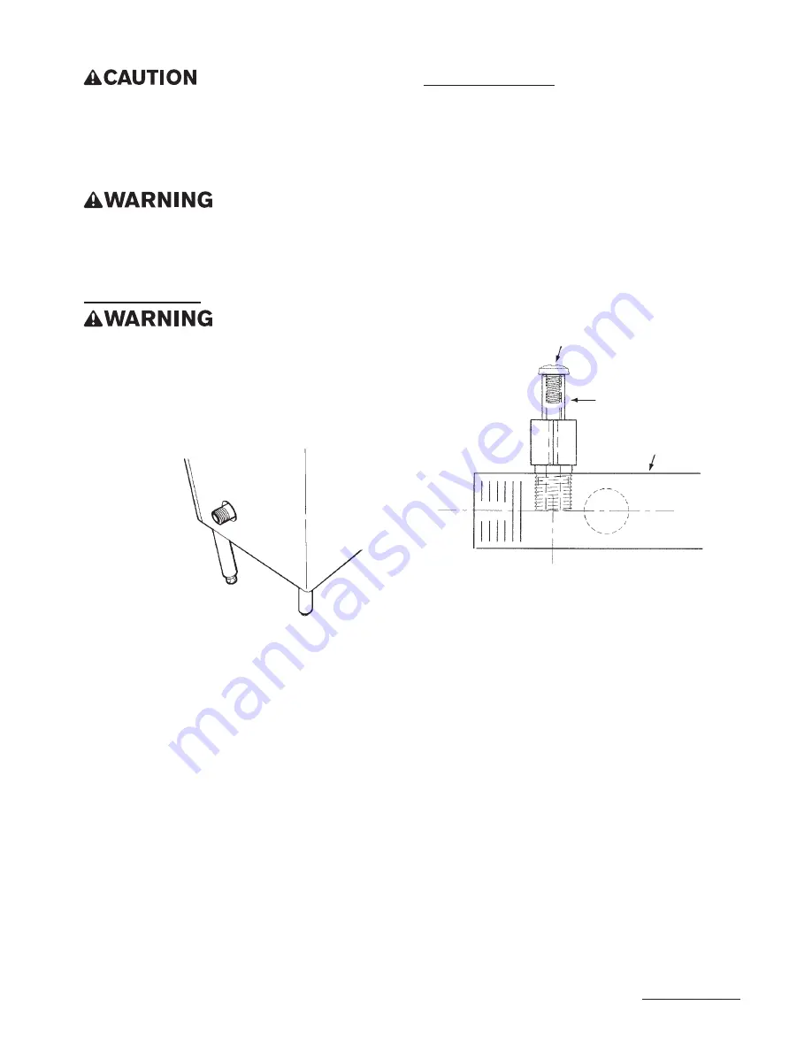
GAS PRESSURE TAP
INSTRUCTIONS FOR USING THE GAS PRESSURE
TAP INCLUDED ON FRYER BATTERY WITH COMMON
MANIFOLD MANUFACTURED AFTER 8/19/10 (Part
#060265)
The gas pressure tap is available on batteried fry-
ers with common manifold piping manufactured after
8/19/10. Keating batteries are often equipped with a
common manifold that supplies gas to each product
in the battery requiring only a single service sup-
ply hook-up. A pressure tap is now provided at this
service hook-up end. Use this tap to confi rm there is
at least 7" WC gas pressure for natural gas and 11"
WC gas pressure for LP (propane) gas when all battery
gas burners are running.
1. Remove the self-sealing screw and hook-up 1/8"
NPT hose to a pressure measuring meter.
2. Turn on the gas supply.
3. Turn on each gas product in the battery so that
all burners are on.
4. Measure the gas supply pressure and ensure
that it is at least 7" WC for natural gas and 11" WC
for LP (propane) gas. (Gas pressure must NOT be
greater than 14" WC whether burners are on or off.)
NOTE:
When installing pressure tap, use gas-rated
sealant on tap threads. Only use sealant on threads
that contact the manifold pipe. Excess sealant may
come loose and clog downstream gas valves or
orifi ces. Clean away any pipe debris or loose sealant
after installing gas pressure tap.
BE SURE TO REPLACE AND TIGHTEN THE SELF-
SEALING SCREW IN THE TAP. EITHER TIGHTEN
SELF-SEALING SCREW BY HAND, OR TIGHTEN WITH
SCREWDRIVER, BUT JUST SLIGHTLY PAST THE POINT
OF GASKET COMPRESSION TO AVOID DAMAGING THE
O-RING SEAL. CHECK THE TAP, AND ALL INSTALLED
PIPING AND GAS CONNECTIONS FOR LEAKS BEFORE
RELEASING THE BATTERY FOR CUSTOMER USE.
5
Figure 2
Main Gas
Connection
Gas Pressure Tap
Common Rear Manifold
w/ Tap Hole
8-32 x 3/8" Screw
Self Seal O-Ring
Figure 3
Gas Pressure
Tap
Summary of Contents for SERIES 2006
Page 34: ... keatingofchicago com 32 14 IFM MODEL 2006 FRONT DRAIN WITHOUT LIGHTED ROCKER SWITCH ...
Page 36: ... keatingofchicago com 34 14 IFM MODEL 2006 CPU BASKET LIFT FRONT DRAIN ...
Page 38: ... keatingofchicago com 36 18 20 IFM MODEL 2007 FRONT DRAIN WITHOUT LIGHTED ROCKER SWITCH ...
Page 42: ......


