background image

MILLIVOLT CHECK 

(FOR QUALIFIED SERVICE TECHNICIANS 

ONLY

)

The millivolt valve is a thermopile self-powered combination gas control. Before checking the millivolt system, the following
operations should be performed and observations made:

1. A genuine Keating millivolt thermostat should be used for millivolt operation.

2. The thermostat leads and all wire connections should be cleaned and tightened to eliminate all unnecessary resistance.

3. If pilot will not remain lit when gas valve knob is released, check automatic pilot.

NOTE:

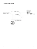
The millivolt system and individual components may be checked with a millivolt meter having a 1-1000MV range.

Conduct each check below by connecting meter test leads to terminals as indicated. All readings are closed circuit.

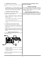
A. BURNER COIL CHECK

(“A” Reading. Thermostat contacts CLOSED - Gas Valve knob “ON”. Main burner should come ON.)

1. If the reading is more than 100 millivolts and the automatic valve still does not come one, replace the valve.

2. If the closed circuit reading (“A” reading) is less than 100 millivolts, determine cause for low reading and proceed as follows:
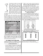
CHECK

TO TEST

CONNECT METER LEADS TO

TERMINALS

THERMOSTAT

CONTACTS

METER READING

SHOULD BE:

A

BURNER COIL

TP

TH

CLOSED

100mV OR MORE

B

THERMOPILE OUTPUT

THTP

TP

OPEN

BETWEEN 325–700mV

C

THERMOSTAT LOAD

THTP

TH

CLOSED

DROPS LESS THAN 80mV

D

AUTOMATIC PILOT DROPOUT

THTP

TP

OPEN

BETWEEN 75-25 mV

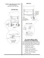
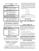
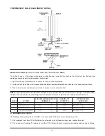
THERMOSTAT BULB PLACEMENT DETAIL

11

Summary of Contents for 37399

Page 1: ...OUBLE SHOOT CHART 9 THERMOSTAT REMOVAL REPLACEMENT 10 11 SERVICE 10 12 WIRING DIAGRAM 13 CONTENTS IMPORTANT Keep a copy of your bill of sale The date on the bill establishes the warranty period should...

Page 2: ...ALLY LOSE ITS ODOR AND PRECAUTIONS SHOULD BE TAKEN TO ASSURE THAT PROPANE GAS IS NOT PRESENT EVEN THOUGH YOU DO NOT DETECT AN ODOR IF THERE IS ANY DOUBT YOU SHOULD CALL YOUR LOCAL PROPANE GAS SUPPLIER...

Page 3: ...RETURN DAMAGED MERCHANDISE TO KEATING FILE YOUR CLAIM AS ABOVE FIRST STEPS POSITIONING Keep appliance area free and clear of any combustibles Position the Miraclean Griddle 6 inches 152mm from any co...

Page 4: ...ure Refer to serial plate for proper gas requirement for your particular model FLEXIBLE GAS CONNECTORS AND QUICK DISCONNECT DEVICES For an appliance equipped with casters The installation shall be mad...

Page 5: ...te to determine if the burner is set up for the proper type gas before connecting the quick disconnect or piping from the building gas supply pipe a Gas pressure at manifold NATURAL GAS 4 0 in W C b G...

Page 6: ...food being cooked more rapidly than other griddle plates because the food is placed directly on the metal surface It is the understanding of this rapid heat transfer that permits the practical and be...

Page 7: ...ventional griddles at least start at lower temperatures You may be able to work the temperature up as you become accustomed to the more rapid cooking of the Miraclean Griddle 2 Cook as usual but after...

Page 8: ...clean surface is irreplacable NEVER USE A GRIDDLE STONE BRICK OR SCREEN TO CLEAN THE MIRACLEAN SURFACE DAMAGE DONE TO THE MIRACLEAN SURFACE BY GRIDDLE STONE BRICK OR SCREEN WILL VOID THE WARRANTY DO N...

Page 9: ...ition your griddle surface 1 Follow cleaning instructions on page 5 2 Heat the MIRACLEAN to 400 F for one hour 3 Lower thermostat to 350 F allowing the MIRACLEAN to cool to about 350 F as is evident w...

Page 10: ...T ELBOW 1 2 004194 14 ORIFICE HOLDER ASSEMBLY REFERENCE ONLY 15 FITTING 1 2 NPT MALE 000615 16 BURNER TUBE 1 2 X 9 1 800 KEATING 17 ELBOW 1 2 x 3 8 006477 18 GAS VALVE MILLIVOLT NATURAL GAS 023625 PRO...

Page 11: ...is in pilot position c Thermostat is not turned on d Low gas presssure e Gas valve failure a Put ON OFF switch to ON position b Turn knob to ON position c Turn thermostat to desired temperature d Set...

Page 12: ...NT 1 Lower the control panel by removing the screws 2 Disconnect the wires on the switch and remove switch 3 Snap the new switch into place and reconnect all wires 4 Return the control panel to its no...

Page 13: ...having a 1 1000MV range Conduct each check below by connecting meter test leads to terminals as indicated All readings are closed circuit A BURNER COIL CHECK A Reading Thermostat contacts CLOSED Gas...

Page 14: ...maximum output is observed Then extinguish pilot and observe meter 2 Dropout of automatic pilot magnet sound should be audible should occur between 75 millivolts and 25 millivolts If dropout occurs ou...

Page 15: ...13 GAS GRIDDLE WIRING DIAGRAM CONTROL PANEL THERMOSTAT ON OFF SWITCH...

Page 16: ...SE OR WARRANTY AGAINST LATENT DEFECTS E XCLUSIONS The warranties provided by Keating of Chicago Inc do not apply in the following instances 1 Defects arising out of or resulting from improper installa...

Page 17: ..._________________________________________________________ ADDRESS __________________________________________________________________________________________________________________ CITY ______________...

Reviews: