

8
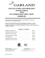
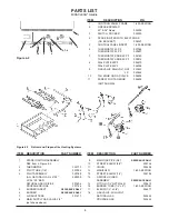
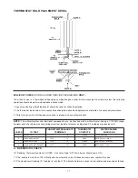
Figure 6-3
Natural and Propane Gas Heating Systems
ITEM
DESCRIPTION
PART NUMBER
1
SPARK IGNITION ASSEMBLY
SEE Item 4, Figure 6-2
2
THERMOPILE
022770
3
PILOT TUBE (1/4”)
007998
4
PILOT ASSEMBLY
029769
(ALL NATURAL GAS, 24”-30”
029599
LP, 24”-39” BEF)
NATURAL GAS ORIFICE
007696
PROPANE ORIFICE
007766
5
BURNER INSERT
REFERENCE ONLY
6
BURNER
REFERENCE ONLY
7
AIR SHUTTERS
031477
8
MAIN SUPPLY GAS VALVE 3/4"
(not shown above)
ITEM
DESCRIPTION
PART NUMBER
9
MAIN GAS PIPE (3/4”)
REFERENCE ONLY
10
STREET ELBOW (3/4”)
005738
11
UNION
002658
12
MANIFOLD
1-800-KEATING
13
STREET ELBOW (1/2”)
004194
14
ORIFICE HOLDER
ASSEMBLY
REFERENCE ONLY
15
FITTING (1/2” NPT MALE)
000615
16
BURNER TUBE (1/2”
X
9”)
1-800-KEATING
17
ELBOW (1/2” x 3/8”)
006477
18
GAS VALVE, MILLIVOLT
NATURAL GAS
023625
PROPANE GAS
023624
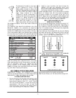
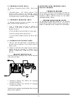
Figure 6-2
ITEM
DESCRIPTION
P/N
1
CONTRON PANEL FRAME
1-800-KEATING
2
GREASE DRAWER
30" & 36" Deep
052505
3
SWITCH, ROCKER
035030
4
SPARK IGNITER WITH ELECTRODE
(NO BRACKET)
008327
5
CONTROL PANEL INSERT
1-800-KEATING
6
THERMOSTAT 400°F
037088
THERMOSTAT 550°F
023897
7
THERMOSTAT KNOB 400°F
004163
THERMOSTAT KNOB 550°F
009914
8
DIAL PLATE 400°F
034870
DIAL PLATE 550°F
058038
9
GAS VALVE MILLIVOLT NAT.
023625
L.P.
023624
10
TAN KNOB ON GAS VALVE
004803
11
SCREW FOR TAN KNOB
004805
(NOT SHOWN)
PARTS LIST
MIRACLEAN
®
Griddle
1
2
3
4
5
6, 7, 8
9
10