background image

28 


 External 

input          Remote 

control 

input 

                                  (Pattern selection, start, stop, pass, AT start

stop) 

 
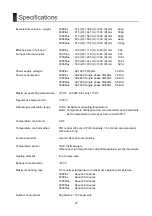
  External output                   Recorder thermocouple output, gas output, event contact output 
                 4 

types, Deodorizer

Smoke exhaust device output, 

                 Running

End

Alarm contact output, 

                                  3-color patrol light output, SD card slot 
 
 Safety 

functions         Overcurrent 

breaker, furnace temperature sensitive cooling fan, 

                 overheat 

detector, 

door 

open/close 

sensor, 

key 

lock 

function 

 
 Program 

controller        Detection 

abnormality controller abnormality, heater disconnection 

                 abnormality, 

temperature 

sensor 

abnormality, 

Memory 

error, 

over 

                                  temperature error 
 

Main options


  Gas introduction unit 1 system      Model 

KDG-300 

                     Applicable 

models 300Plus, 

500Plus 

                     Flowmeter 

    Nitrogen 

2L/min 


Oxygen, argon possible


                                          1 inlet 
                 Model 

KDG-1500 

                     Applicable 

model 

 1500 

Plus 

                     Flowmeter 

    Nitrogen 

5L/min 


Oxygen, argon possible


                                          2 inlets 
                 Model 

KDG-3000 

                     Applicable 

model 

 3000 

Plus 

                     Flowmeter 

    Nitrogen 

10L/min 


Oxygen, argon possible


                                          2 inlets 
                 Model 

KDG-5000 

                     Applicable 

model 

 5000 

Plus 

                     Flowmeter 

    Nitrogen 

20L/min 


Oxygen, argon possible


                                          2 inlets 


Please contact us regarding two gas introduction units. 


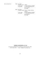
 Deodorizer 

           Model 

KDF-ES71 

                     Applicable 

model 

 300Plus 

                                          Power supply    AC100V 

300VA 

                 Model 

KDF-ES72 

                     Applicable 

models 500Plus, 

1500Plus, 

3000Plus, 

                              5000Plus 
                                          Power supply    AC200V 

300VA 


Summary of Contents for 1500-Plus

Page 1: ...ctric Furnace Plus series Before using the unit please read the manual thoroughly and understand the capabilities and proper usage for this machine Please keep this manual in an easily accessible location for future reference W1022700 0 ...

Page 2: ......

Page 3: ...Installation location environment 11 Wiring work 11 Installation of hearth plate 11 Installation of exhaust guide and exhaust port plug 11 Connection of rear terminals 12 T C OUTPUT OPTION 12 CLEANER 12 RELAY CONTACT OUTPUT 12 REMOTE INPUT 13 GAS UNIT OUTPUT 13 SIGNAL LAMP OUTPUT 13 Turn on the power 14 Program controller operation overview 14 Standby mode 15 Explanation of main display 15 Explana...

Page 4: ...1 Check and change program contents 21 PID auto tuning operation 21 About SD card operation record 21 Operation record data 22 Initial Setting Mode 22 Buzzer volume setting 22 Temp Calibration setting 22 Back Light setting 23 Sensor Type setting 23 SD Error setting 23 Abnormal Temp Rise setting 23 Maintenance mode 23 Explanation of main display 24 PID edit mode 24 Explanation of main display 24 Ex...

Page 5: ...s on material resources Please read them carefully prior to your actual machine operation WARNING CAUTION Failure to follow or ignorance of the directions may cause severe injury or death Failure to follow or ignorance of the directions may cause injuries or damages to material properties This symbol indicates that the action is prohibited This symbol indicates the content that calls attention or ...

Page 6: ...n only be used in Japan When installing this unit keep it 100 cm above the ceiling and at least 30 cm away from walls and equipment in other cases Also do not place any objects on the top surface of this machine It may cause fire or malfunction Do not install in a place where flammable materials may fall onto the projector or fly It may cause a fire Do not install in places subject to rain or wate...

Page 7: ...f the power switch or breaking the breaker The case of this machine will not be cooled and may cause burns Fixed the wiring and piping connected to this machine so that they will not be caught It may cause electric shock fire or gas leak Keep paper cloth curtains vinyl hair spray gasoline benzine thinner alcohol and other flammable materials away from this machine Also do not install this unit on ...

Page 8: ... during use but this is not a defect There is no problem with performance so use it as is Standard accessories Exhaust guide 1pc Exhaust port plug 1pc Hearth plate 1pc One set of 2 for 5000Plus AC cord 1pc Except 300Plus 500 1500Plus 3m 3000 5000Plus 5m For cleaners and Exhaust gas devices Extension cable 1pc Only for 3000 5000Plus Instruction Manual This document 1booklet We recommend you to save...

Page 9: ...n the power Liquid crystal panel Display part of the color liquid crystal Operation panel Program operation Start processing SD card slot side Use SD card to edit programs update this unit etc Exhaust port The exhaust port is open near the center of the furnace top surface Deodorizer and smoke exhaust when connecting gas is exhausted from this hole Usually the exhaust port plug provided is packed ...

Page 10: ...tinel thermocouples Cleaner smoke exhaust device output Power outlet for optional cleaner and smoke exhaust device The 3000 and 5000Plus are connected using the included extension cable Do not connect anything other than our designated cleaner and smoke exhaust device External output terminal The terminal block that outputs information inside the main unit to the outside Remote terminal The connec...

Page 11: ...insulation to improve the thermal efficiency and temperature distribution For this reason if the processed product contacts the hot plate it may be damaged so be careful not to contact the left and right hot plates when putting in or taking out the processed product Also depending on the type of gas or liquid generated from the heat treated material damage to the heat insulating material or breaka...

Page 12: ...e AL2O3 protective film formed on the surface of the heating element or that reacts with the protective film to lower the melting point is harmful to the heating element S sulfur Use in an atmosphere containing H2S or SO2 is not preferable because it reacts with S to lower the melting point Halogen salt Halogen elements such as Cl and F and salts of alkali metals such as Na and K are all harmful b...

Page 13: ...wer equipment prepared exclusively for this machine The green wire of the power cord becomes the ground wire Be sure to connect the ground wire to a properly constructed ground terminal Installation of hearth plate Please lay the attached hearth plate on the bottom of the furnace For 5000Plus lay two attached hearth plates on the bottom of the furnace If you place the fired product directly on the...

Page 14: ...usting device cannot be used at the same time 300Plus Deodorizing device ES71 Smoke exhausting device VF71 500Plus 1500Plus 3000Plus 5000Plus Use the extension cable included with 3000 and 5000Plus For connection of the deodorizer and smoke exhaust device follow the instruction manual of the deodorizer and smoke exhaust device RELAY CONTACT OUTPUT contact output terminal Event output and each oper...

Page 15: ... 3 Course selection 2 4 Course selection 2 5 DC5 24V GND GAS UNIT OUTPUT A connector for connecting the optional gas introduction unit By connecting the gas introduction unit to this connector the gas can be introduced as set in the program items gas 1 and gas 2 The following options can be connected For the connection method of the gas introduction unit follow the instruction manual of the gas in...

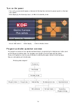
Page 16: ...programming the temperature control each event and each condition value The program can program up to 100 segments per pattern There are 50 patterns and it is easy to identify by entering the pattern name for each purpose Now we will explain each mode below Mode system diagram Screen data version model display control software version Power on Title display Standby mode Program mode Copy mode Init...

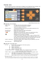
Page 17: ...om being interrupted The fan will stop and the enclosure will become hot which is dangerous START STOP Lamp Lights during operation Also it flashes during each operation of the auto tuning and soak stop KEY LOCK Lamp Lights during key lock Explanation of operation keys F1 F4 Function keys The displayed on the screen operates F1 Switch to program mode F2 Switch to copy mode F3 Switch to initial set...

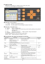
Page 18: ...ern name Character English uppercase number Number of characters 16 single byte characters Input the pattern name Enterable symbols Blank Temp 0 to 1150 other than 5000Plus 0 1100 5000Plus Segment set temperature 0 Time 0 00 to 99 59 hour min Segment set time 0 00 PID group 0 9 A PID group selection A is auto A SS 0 99 0 is no SS operation Soak stop set temperature Set the temperature range when y...

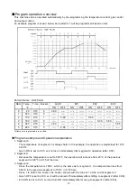
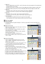
Page 19: ...segment 0 is always held In the example the operation is maintained for 0 10 at 20 Gas 1 ON is set to 0 00 so it turns on immediately after segment 0 operation after 0 00 2 Segment 1 Because the temperature is set to 500 the operation will increase from 20 of the previous segment to 500 in 0 15 of the time 3 Segment 2 Since the temperature is 700 which is the same as for segment 1 the temperature ...

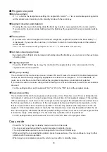
Page 20: ...e input 1 When the cursor is Seg0 press the Up key to move the cursor to the pattern name 2 Use the left right keys to move to the place you want to input and press UP or DOWN Press the key to select the character number alphabet symbol you want to enter In our example we type KDF PLUS Screen 1 3 When input is complete press the down key to return the cursor to Seg0 Input of other items 1 Use the ...

Page 21: ...omatically selected If you want to switch to manual change the PID setting to 0 9 If set to Manual the set PID set constants are used For the setting method set the value of 0 9 or A in the PID item of the program mode Soak stop setting The controller of this machine progresses with priority on time Therefore even if the set temperature is not reached it will move to the next segment when the set ...

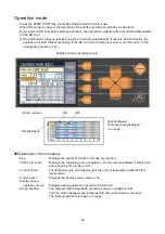
Page 22: ...ation of main display Seg Displays the segment number currently in progress TOTAL Time left Displays the remaining time of operation You can switch between TOTAL time and remaining time in Seg units Control Temp The temperature is controlled so that the current temperature matches this temperature Power outlet Displays the heater power output in Display during operation record Displayed during ope...

Page 23: ...he pattern selection screen is displayed Select the pattern you want to edit and press the enter key Changes made to patterns other than those during operation are stored in memory PID auto tuning operation If the amount of the burned material changes temperature control may be uneven so perform the PID auto tuning operation if necessary Normally there is no problem with the constants initially se...

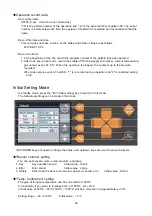
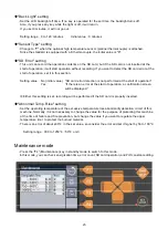
Page 24: ...topped the contents up to the stop are recorded For gas output event AT and SS 1 is recorded during operation and 0 is recorded during stop Initial Setting Mode In standby mode press the F3 initial setting key to switch to this mode The following settings can be made in this mode UP DOWN keys are used to change the value and up down keys are used to move the items Buzzer volume setting You can set...

Page 25: ...l value SD card error detection is not performed at the start of operation Yes If there is an error at the start of operation a confirmation screen will be displayed Either this setting is set recording will be performed if the SD card is properly inserted Abnormal Temp Rise setting Set the operating temperature of the excessive temperature rise abnormality detection circuit of this machine Normal...

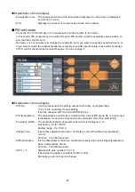
Page 26: ...tion of main display PID No 0 to 9 correspond to the setting number at the time of programming 10 to 19 are constants for auto setting It can be changed with the UP and DOWN keys PID temperature The temperature at which the constant of the current PID group No is auto tuned is displayed It cannot be changed by any operation other than auto tuning Proportion Width The proportional band of proportio...

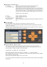
Page 27: ...his mode In this mode you can read and write the program contents and write the maintenance information contents to the SD card When you want to edit the program contents on the PC back up the program contents or when there is a failure please use it when you send us the usage data Program contents Export Import Insert the SD card into the slot and press the F2 key for writing and the F4 key for r...

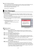
Page 28: ...equipment Warning content Warning No 2 Controller error Displayed when the controller operates abnormally due to the influence of noise Almost always recovers when the power is turned on again but if it occurs frequently repair is required Warning No 5 Heater disconnection error The heater may be broken Needs repair Warning No 6 Temperature sensor error The temperature sensor may be broken or defe...

Page 29: ... 60Hz 8 0kVA Maximum operating temperature 1150 5000 Plus only 1100 Regular use temperature 1000 Operating temperature range 100 Maximum operating temperature Note Temperature distribution and control performance deteriorate as the temperature decreases from around 300 Temperature control unit 0 5 Temperature control method PID control 20 sets of PID constants 10 of which are automatic with auto t...

Page 30: ...re sensor abnormality Memory error over temperature error Main options Gas introduction unit 1 system Model KDG 300 Applicable models 300Plus 500Plus Flowmeter Nitrogen 2L min Oxygen argon possible 1 inlet Model KDG 1500 Applicable model 1500 Plus Flowmeter Nitrogen 5L min Oxygen argon possible 2 inlets Model KDG 3000 Applicable model 3000 Plus Flowmeter Nitrogen 10L min Oxygen argon possible 2 in...

Page 31: ...ant duct 2 5m when extended Duct clamp Model KDF VF72 Applicable models 500Plus 1500Plus 3000Plus 5000Plus Power supply AC200V 34VA 50Hz 37VA 60Hz Accessories φ75 heat resistant duct 2 5m when extended Duct clamp 24 3 Kisshoin Ishiharakyomichi cho Minami ku Kyoto 601 8356 JAPAN TEL 81 75 672 2124 E mail info denken highdental co jp ...

Reviews: