background image

11 MAINTENANCE AND UPKEEP

11.1 Failure information and code

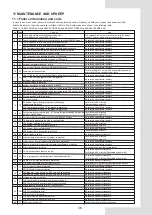
In case the unit runs under abnormal condition, failure protection code will display on both control panel and wired controller, 

and the indicator on the wired controller will flash with 1Hz. The display codes are shown in the following table:
Table11-1 

KEM-75 DRS5 KH

 and 

KEM-90 DRS5 KH

 and 

KEM-140 DRS5 KH

 and 

KEM-180 DRS5 KH


No. Code

Content

Note

1

E0 75&140 Model Main control Model setting error

(Other Model Main control EPROM error)

The capability selection is inconsistent with the actual

model. Power on again after setting correctly

2

E1 Phase sequence error of main control board check(for 90&180 model)

Recovered upon failure recovery

Communication failure between master and the HMI

Recovered upon failure recovery

Communication failure between master and slave
2E2 Communication failure between main board and slave board

Recovered upon failure recovery

4

E3 Total water outlet temperature sensor failure (main unit valid)

Recovered upon failure recovery

5

E4 Unit water outlet temperature sensor failure

Recovered upon failure recovery

1E5 condenser tube temperature sensor T3A failure

Recovered upon failure recovery

2E5 condenser tube temperature sensor T3B failure

Recovered upon failure recovery

7

E6 Water tank temperature sensor T5 failure

Recovered upon failure recovery

8

E7 Ambient temperature sensor failure

Recovered upon failure recovery

9

E8 Power supply phase sequence protector output error

Recovered upon failure recovery

10

E9 Water flow detection failure

Failure locking for 3 times in 60 minutes(Recovered by

power off or Wired controller clear fault)

1Eb-->Taf1 the pipe of the tank antifreeze protection sensor failure

Recovered upon failure recovery

2Eb-->Taf2 cooling evaporator low-temperature

antifreeze protection sensor failure

Recovered upon failure recovery

12

EC Slave unit module reduction

Recovered upon failure recovery

13

Ed system discharge temperature sensor failure

Recovered upon failure recovery

1EE EVI plate heat exchanger refrigerant temperature T6A sensor failure Recovered upon failure recovery
2EE EVI plate heat exchanger refrigerant temperature T6B sensor failure Recovered upon failure recovery

15

EF Unit water return temperature sensor failure

Recovered upon failure recovery

16

EP Discharge sensor failure alarm

Recovered upon failure recovery

17

EU Tz  sensor failure

Recovered upon failure recovery

P0 System high-pressure protection or discharge

temperature protection

for 3 times in 60 minutes

(Recovered by power off)

1P0 Compressor module 1 high pressure protection

Recovered upon failure recovery

2P0 Compressor module 2 high pressure protection

Recovered upon failure recovery

19

P1 System low pressure protection

or Severe refrigerant leakage protection

only for 75&140 model

for 3 times in 60 minutes

(Recovered by power off)

20

P2 Tz total cold outlet temperature too high(for 90&180 model)

Recovered upon failure recovery

21

P3 T4 ambient temperature too high in cooling mode

Recovered upon failure recovery

1P4 System A current protection
2P4 System A DC bus current protection
1P5 System B current protection
2P5 System B DC bus current protection

24

P6 Inverter module failure

Recovered upon error recovery

25

P7 High temperature protection of system condenser

for 3 times in 60 minutes

(Recovered by power off)

26

P9 Water inlet and outlet temperature difference protection

Recovered upon failure recovery

27

PA Abnormal water inlet and outlet temperature difference protection

Recovered upon failure recovery

28

Pb Winter antifreeze protection

Reminder code, non fault or protection
Recovered upon error recovery
for 3 times in 60 minutes(Recovered by power off)
Recovered upon error recovery
for 3 times in 60 minutes(Recovered by power off)

31

PH Heating T4 too high temperature protection

Recovered upon error recovery

32

PL Tfin module temperature too high protection

for 3 times in 100 minutes(Recovered by power off)

1PU DC fan A module protection

Recovered upon failure recovery

2PU DC fan B module protection

Recovered upon failure recovery

1bH:Module 1 relay blocking or 908 chip self-check failed

Recovered upon error recovery

1bH:Module 2 relay blocking or 908 chip self-check failed

Recovered upon error recovery

35

H5 Voltage too high or too low

Recovered upon error recovery

1H9 Compressor A inverter module is not matched

Recovered upon error recovery

2H9 Compressor B inverter module is not matched

Recovered upon error recovery

37

HC High pressure sensor failure(for 75&140 model)

Recovered upon error recovery

1HE No inset A valve error

Recovered upon error recovery

2HE No inset B valve error

Recovered upon error recovery

3HE No inset C valve error

Recovered upon error recovery

1F0 IPM module A transmission error

Recovered upon error recovery

2F0 IPM module B transmission error

Recovered upon error recovery

40

F2 Superheat insufficient

Wait at least 20min before recovering

Cooling evaporator pressure too low

3

E2

6

E5

29

PC

for 3 times in 60 minutes

(Recovered by power off)

for 3 times in 60 minutes

(Recovered by power off)

34

bH

14

EE

18

P0

22

P4

33

PU

23

30

PE Cooling evaporator low temperature antifreeze protection

xH9

11

Eb

P5

HE

F0

36

38

39

36

Summary of Contents for KEM-75 DRS5 KH

Page 1: ...our air conditioner Before using your air conditioner please read this manual carefully and keep it for future reference OWNER S INSTALLATION MANUAL DC Inverter Air cooled Modular Chiller KEM 75 DRS5...

Page 2: ...trong breeze 6 1 6 2 6 3 6 4 6 5 PRECAUTIONS ON INSTALLATION 11 7 CONNECTION DRAWING OF PIPELINE SYSTEM 13 11 8 15 20 30 Main parts of the uint Opening the uint Outdoor unit PCBs Electric wiring Water...

Page 3: ...1 5 11 6 11 7 11 8 11 9 11 10 11 11 11 12 11 13 36 38 38 38 38 39 39 39 39 44 40 41 44 39 38 Failure information and code Data display of wired controller Care and maintenance Removing scale Winter sh...

Page 4: ...n above 15 should be added in the water system otherwise the unit and the water system will be damaged Outlet water temperature Outlet water temperature G KEM 75 DRS5 KH KEM 140 DRS5 KH KEM 75 DRS5 KH...

Page 5: ...used to alert against unsafe practices Indicates situations that could only result in accidental equipment or property damage NOTE Explanation of symbols displayed on the indoor unit or outdoor unit...

Page 6: ...tidy the wires so that the front panel can be securely fastened If the front panel is not in place there could be overheating of the terminals electric shocks or fire After completing the installation...

Page 7: ...Children should not play with the unit Cleaning and user maintenance should not be done by children without supervision This appliance is intended to be operated by expert or trained users in shops i...

Page 8: ...can be fastened on the foundation reliability 7 If the unit is installed on a roof the roof must be strong enough to bear the weight of the unit and the weight of maintenance personnel The unit can b...

Page 9: ...6 PRECAUTIONS ON INSTALLATION 6 1 Outline dimensional drawing Fig 6 1 Outline dimensional 06 Front view Left view Top view...

Page 10: ...will increase by 135mm approximately Model A B C D E F KEM 90 DRS5 KH 2220 1135 2315 910 255 270 Table 6 1 KEM 75 DRS5 KH 2000 960 1770 816 190 270 KEM 140 DRS5 KH 2220 1135 2300 910 185 380 KEM 180...

Page 11: ...ss than the static pressure outside the fan The space between the unit and sunk fence or Persian blinds should also meet the requirement 3 If the unit needs to operate in winter and the installation s...

Page 12: ...ructed on solid ground or on structures of sufficient strength to support the units weight 2 Bases should be at least 200mm high to provide sufficient access for installation of piping Snow protection...

Page 13: ...sure trouble free operation of the equipment Otherwise accumulated snow will block the air flow and may cause equipment problems Check the installation site thoroughly do not install the equipment und...

Page 14: ...AME Air inlet Water outlet wire controller It can be placed indoors Expansion tank Gas liquid separator Induction pump Table 8 1 Stop valve Pressure gauge Water flow switch Gate valve Flexible joint Y...

Page 15: ...M 90 DRS5 KH Picture just use to show the key component relative position Fig 8 3 Main parts of KEM 140 DRS5 KH Picture just use to show the key component relative position Fig 8 4 Main parts of KEM 1...

Page 16: ...nger Cover 4 give access to the electrical parts Cover 5 6 give access to the hydraulic compartment Cover 1 Cover 2 Cover 3 Cover 6 Cover 5 Cover 4 Fig 8 7 Doors of KEM 90 DRS5 KH KEM 140 DRS5 KH Cove...

Page 17: ...2 Door 3 Door 4 Door 5 Door 6 Door 7 Door 8 Door 9 Door 10 Door 1 2 3 9 10 give access to the compartment of water pipes and water side heat exchanger Door 4 5 give access to the hydraulic compartment...

Page 18: ...rt value of the alarm actually detected is ON OFF but not 220 240V control power supply so special attention should be paid when installing the alarm signal output CN68 Pump 220 240V control power sup...

Page 19: ...enser CN30 T4 outdoor ambient temperature sensor CN45 Taf2 Water side antifreeze temperature sensor CN16 T3B pipe temperature sensor of the condenser CN38 Tp2 DC inverter compressor B discharge temper...

Page 20: ...ate of the compressor Attention the control port value of the COMP STATE actually detected is ON OFF but not 220 240V control power supply so special attention should be paid when installing the light...

Page 21: ...solenoid valve CN80 Injection solenoid valve of compressor system B CN47 Injection solenoid valve of compressor system A CN5 Water side heat exchanger heaters connection CN40 Multi function solenoid...

Page 22: ...essor inverter module communication ports CN300 Program burn in port WizPro200RS programming device IC10 EEPROM chip CN1 temperature sensors input port T4 outdoor ambient temperature sensor T3A T3B pi...

Page 23: ...power supply whose voltage should conform to rated voltage Wiring construction must be conducted by the professional technicians according to the labeling on the circuit diagram The power wire and the...

Page 24: ...2 1 DSP1 DSP2 8 4 2 KEM 75 DRS5 KH and KEM 140 DRS5 KH DIP switch buttons and digital display positions of uints Fig 8 13 Display positions 8 4 2 KEM 90 DRS5 KH and KEM 180 DRS5 KH DIP switch buttons...

Page 25: ...cal standards b Copper core wires must be used Fig 8 15 1 Electrical wiring precaution a Fig 8 15 2 Electrical wiring precaution b c It is advisable to use 3 core shielded cables for uint to minimize...

Page 26: ...arrester Power distribution transformer Wrong Manual switch Fuses Power 380 415V 3N 50Hz Fig 8 16 Requirements of power supply wiring Uint NOTE Do not connect the grounding wire of the lightning arres...

Page 27: ...S5 KH 0 electric control box ON OFF port ON Power DC 12V Main control board is provided 0 electric control box ON OFF port OFF Power DC 12V Main control board is provided Fig 8 21 1 Wiring of ON OFF w...

Page 28: ...ll cause the units to malfunction b The shielding nets at both ends of the shielded wire must be grounded Alternatively the shielding nets of all shielded wires are interconnected and then connected t...

Page 29: ...the actual parameter of products and national Contactor Contactor Power Transformer OUTPUT 8 5 V Contactor MAIN CONTROL WIRECONTROLLER X Y X Y X Y XT3 L1 L 2 L3 POWER 380 415V 3N 50Hz ENC1 AC1 AC2 MAI...

Page 30: ...AC2 RD YE BK BR WH MONITOR WIRECONTROLLER CN60 5 6 7 8 9 10 11 12 5 6 7 8 9 10 11 12 CN74 CN61 WH RD YE BK BR RD YE BK BR WH MONITOR WIRECONTROLLER X Y X Y X Y X Y E X Y E CN25 XT3 CN30 XT3 CN2 CN83 C...

Page 31: ...ing to the actual parameter of products and national Contactor Contactor Power Transformer OUTPUT 8 5 V MAIN CONTROL WIRECONTROLLER X Y X Y X Y Contactor XT3 POWER 380 415V 3N 50Hz POWER 380 415V 3N 5...

Page 32: ...1 F indicate slave units 29 Fig 8 28 Networking communication schematic of main unit and auxiliary unit for KEM 180 DRS5 KH Contactor Contactor for pipeline Contactor for water tank 7 MONITOR WIRECON...

Page 33: ...so they need to be purchased by the user k All low positions of the water system should be providedwith drainage ports to drain water in the evaporator and the system completely and all high position...

Page 34: ...S5 KH model uses hoop connection For the specifications of the water pipes and screw thread see the Table 8 5 below Table 8 5 kW is the unit for cooling capacity and L is the unit for G water flow in...

Page 35: ...rated water flow in terms of multi connect the units that water flow must no less than total units rated water flow b Select the left of the pump H h1 h2 h3 h4 H The lift of the pump h1 Main unit wate...

Page 36: ...ine 2 Table of diameter parameters of main inlet and outlet pipes 2 Applicable standard of water quality for the unit PH value Total hardness Conductivity Sulfide ion Chloride ion Ammonia ion Sulfate...

Page 37: ...er outlet temperature sensing bulb target flow controller and auxiliary electric heater are under control of the main module One wired controller and one target flow controller are required and connec...

Page 38: ...ent Wire capacity is meeting for requirement Switch capacity is meeting for requirement Fuse capacity is meeting for requirement Voltage and frequency are meeting for requirement Connecting tightly be...

Page 39: ...on for 3 times in 60 minutes Recovered by power off 1P0 Compressor module 1 high pressure protection Recovered upon failure recovery 2P0 Compressor module 2 high pressure protection Recovered upon fai...

Page 40: ...A 2 for Compressor B Recovered upon error recovery 53 xL7 phase loss x 1or 2 1 for Compressor A 2 for Compressor B Recovered upon error recovery 54 xL8 frequency change over 15Hz x 1or 2 1 for Compre...

Page 41: ...be made on the set points on site Regularly check whether the electric connection is loose and whether there is bad contact at the contact point caused by oxidation and debris etc and take timely mea...

Page 42: ...nt of refrigerant will be affected by the ambient temperature If the required amount has not been reached but no more injection can be done make the chilled water circulate and start up the unit for i...

Page 43: ...afety valve safety valve liquid vapor separator The air outlet of safty valve must be connected to the appropriate pipe which can direct the leaking refrigerant to the appropriate place for discharge...

Page 44: ...the period that the work is carried out The ventilation should safely disperse any released refrigerant and preferably expel it externally into the atmosphere 8 Checks to the refrigeration equipment W...

Page 45: ...be repeated until no refrigerant is within the system When the final OFN charge is used the system shall be vented down to atmospheric pressure to enable work to take place This operation is absolutel...

Page 46: ...gerants are removed safely When tranferring refrigerant into cylinders ensure that only appropriate refrigerant recovery cylinders are employed Ensure that the correct numbers of cylinders for holding...

Page 47: ...C C MPa MPa V A C C C C A High pressure Low pressure Voltage Current Inlet dry bulb Outlet dry bulb Inlet Outlet 1 Check temperature of chilled water or hot water Inlet Outlet 2 Check air temperature...

Page 48: ...unit Net Weight Operation Weight Packing dimension Type Chargeing volume kg Waterflow volume m 3 h cooling Hydraulic resistance lose kPa Water side heat exchanger Max pressure MPa Min pressure MPa Inl...

Page 49: ...ne or water flow rate outdoor side heat exchanger Sound power level indoors outdoors Emissions of nitrogen oxides if applicable GWP of the refrigerant Standard rating conditions used Contact details I...

Page 50: ...ow rate outdoor side heat exchanger Sound power level indoors outdoors Emissions of nitrogen oxides if applicable GWP of the refrigerant Standard rating conditions used Contact details If Cdc is not d...

Page 51: ...ow rate outdoor side heat exchanger Sound power level indoors outdoors Emissions of nitrogen oxides if applicable GWP of the refrigerant Standard rating conditions used Contact details If Cdc is not d...

Page 52: ...outdoor side heat exchanger Sound power level indoors outdoors Emissions of nitrogen oxides if applicable GWP of the refrigerant Standard rating conditions used Contact details If Cdc is not determine...

Page 53: ...tandby mode Crankcase heater mode Capacity control Fixed Variable Variable Sound power level indoors Sound power level outdoors Contact details 1 For heat pump space heaters and heat pump combination...

Page 54: ...andby mode Crankcase heater mode Capacity control Fixed Variable Variable Sound power level indoors Sound power level outdoors Contact details 1 For heat pump space heaters and heat pump combination h...

Page 55: ...e Standby mode Crankcase heater mode Capacity control Fixed Variable Variable Sound power level indoors Sound power level outdoors Contact details 1 For heat pump space heaters and heat pump combinati...

Page 56: ...de Standby mode Crankcase heater mode Capacity control Fixed Variable Variable Sound power level indoors Sound power level outdoors Contact details 1 For heat pump space heaters and heat pump combinat...

Page 57: ......

Page 58: ......

Page 59: ...16127100A09250 V D...

Page 60: ......

Reviews: