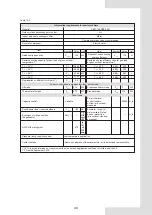
12 APPLICABLE MODELS AND MAIN PARAMETERS
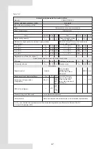
Table 12-1
Model
KEM-75 DRS5 KH
KEM-90 DRS5 KH
KEM-140 DRS5 KH
380-415V 3N~ 50Hz
Control of wired controller, auto startup, running state display, failure alert etc.
High or low pressure switch, freeze-proof device, water flow volume controller,
Overcurrent device, power phase sequence device etc.
kW
kW
kW
A
kW
A
Cooling capacity
Heating capacity
Standard cooling input
Cooling rated current
Standard heating input
Heating rated current
Power supply
Operation control
Safety device
Water pipe system
Air side heat exchanger
Outline dimension
N.W. of the unit
Net Weight
Operation Weight
Packing dimension
Type
Chargeing volume kg
Waterflow volume m
3
/h(cooling)
Hydraulic resistance
lose kPa
Water side heat
exchanger
Max. pressure MPa
Min. pressure MPa
Inlet and outlet pipe dia.
Type
Air flow volume m
3
/h
L mm
W mm
H mm
kg
kg
L × W × H mm
R32
Plate heat exchanger
1.0
0.15
Fin coil model
28500
2000
960
1770
475
485
2085×1030×1890
DN50
DN50
35000
2220
1135
2315
686
700
2250×1180×2445
69.7
75.4
27.3
42.0
24.3
37.3
82.0
90.0
28.3
47.0
29.0
48.0
DN65
Refrigerant
129.5
138.6
51.4
79.0
45.6
70.0
9.0
12.0
156
16.0
14.1
220
15.5
22.4
94
50000
2220
1135
2300
746
776
2250×1180×2445
Waterflow volume m
3
/h(heating)
12.9
15.5
23.7
KEM-180 DRS5 KH
DN80
163.0
181.2
57.7
89.0
59.1
91.0
16.0*2
28.2
31.0
205
70000
2220
2752
2413
1500
1520
2245*2810*2446
45


