If multiple units are connected in cascade, the unit address should be set on the DIP switch ENC4. With 0-F being valid, 0 indicates
the master unit and 1-F indicate slave units.
29
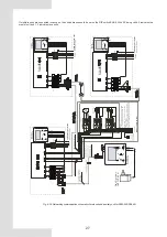
Fig. 8-28 Networking communication schematic of main unit and auxiliary unit for
KEM-180 DRS5 KH
Contactor
Contactor
for pipeline
Contactor
for water tank
7
MONITOR
WIRECONTROLLER
MONITOR
WIRECONTROLLER
7
7
MAIN CONTROL
WIRECONTROLLER
MAIN CONTROL
WIRECONTROLLER
Contactor
Contactor
for pipeline
Contactor
for water tank


