background image

Assembly instructions Everest

®

 engine Base Camp 4140

6 Settings for service

 | 

6.3 Do a reference run

6.3 Do a reference run

Note

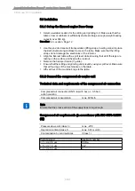
After installing the KaVo Everest Engine or changing a power supply, each axis

must separately do a reference run.


X


Z


Y


A


B


The five axes and their positions:

▪ Spatial axis X (horizontal)

▪ Spatial axis Y (orthogonal)

▪ Spatial axis Z (vertical)

▪ Rotary axis A (gripping yoke)

▪ Rotary axis B (double spindle)

▶ In the CNC/MMI software, go to the menu "MANual" and click the button "Re‐

ference run" (F4).

▶ Click the button "Z axis" (F3), and press the function key Start on the control

panel. Make sure that only the button "Z axis" (F3) has a green background. All

of the other axes must be deactivated.

The Kavo Everest Engine does a reference run in the Z direction.

▶ Click the button "Y axis" (F2), and press the function key Start on the control

panel. Make sure that only the button "Y axis" (F2) has a green background. All

of the other axes must be deactivated.

The Kavo Everest Engine does a reference run in the Y direction.

▶ Click the button "X axis" (F1), and press the function key Start on the control

panel. Make sure that only the button "X axis" (F1) has a green background. All

of the other axes must be deactivated.

The Kavo Everest Engine does a reference run in the X direction.

24/51

Summary of Contents for Everest engine Base Camp 4140

Page 1: ...Assembly instructions Everest engine Base Camp 4140 Always be on the safe side...

Page 2: ...Sales KaVo Dental GmbH Bismarckring 39 D 88400 Biberach Tel 49 7351 56 0 Fax 49 7351 56 1488 Manufacturer Kaltenbach Voigt GmbH Bismarckring 39 D 88400 Biberach www kavo com...

Page 3: ...5 3 3 Adapt the voltage 14 5 3 4 Connect the system 15 5 3 5 Connect the cooling lubricant 17 5 3 6 Connect the computer network 19 6 Settings for service 21 6 1 Overview of control panel 21 6 2 Star...

Page 4: ...alibration program Basecamp_calibration exe 45 7 4 2 Run the calculation with Basecamp_calibration exe 45 7 4 3 Change cycle parameter P0051 46 7 4 4 Change the machine parameter Y0 46 7 5 Back up and...

Page 5: ...ion GA Instructions for use PA Care instructions MA Assembly instructions TA Technician s instructions STK Safety check IEC International Electrotechnical Commission RA Repair instructions EMC Electro...

Page 6: ...1 User instructions 1 2 Service 1 2 Service Service hotline 49 7531 56 2100 Service Everest kavo com User hotline 49 7531 56 2200 Please indicate the product serial number or version number Additiona...

Page 7: ...11 9 10 7 5 4 8 12 13 KaVo Everest engine Base Camp 4140 Milling grinding unit Gripping yokes and tension rings Software and operating instructions Maintenance unit incl pressure regu lator for compr...

Page 8: ...rest engine Base Camp 4140 2 Scope of delivery and packaging 2 1 Scope of supply for the Everest engine Base Camp Consumables no illustration Allen key Wrench size Mat no 2 5 mm 1 005 0600 5 mm 1 004...

Page 9: ...eight Approx 305 kg gross and approx 280 kg net Packing piece 2 Industrial PC with keyboard mouse monitor and power supply Length 1 200 mm Width 820 mm Height 760 mm Weight Approx 92 kg gross Packaged...

Page 10: ...rvance The optional step contains necessary measures for avoiding hazards 3 1 3 Description of hazardous steps Safety instructions with three hazard levels are used in this document for avoiding perso...

Page 11: ...ructions Everest engine Base Camp 4140 4 Product description 4 1 KaVo Everest engine Base Camp 4 Product description 4 1 KaVo Everest engine Base Camp Milling grinding unit PC Monitor and Keyboard Con...

Page 12: ...Everest engine Base Camp 4140 4 Product description 4 1 KaVo Everest engine Base Camp ID reader and adapter max Everest R engine min Coolant lubricant unit Power pack with power switch to turn off th...

Page 13: ...ined by KaVo Note No additional software may be installed on the control computer for the KaVo Eve rest engine Base Camp Note If the KaVo Everest engine has been transported and delivered at very low...

Page 14: ...ned personnel may move the milling grinding unit Since the milling and grinding unit is so heavy make sure that the table or row of cabinets is sufficiently stable and large enough weight bearing capa...

Page 15: ...egs are resting on the surface and fixed with a locknut Remove the transport brace Y guide Ensure that the milling and grinding unit is level by using a spirit level Make sure that all four legs of th...

Page 16: ...use Set air pressure on the manometer of the maintenance unit to 5 5 bar 5 3 3 Adapt the voltage Ensure that the nominal voltage and nominal frequency of the milling grinding unit corresponds to the n...

Page 17: ...cting up appliances proceed with the greatest care and attention so as to avoid any damage to cables and plug fit connections CAUTION Electrical current Electrical shock Make sure that the system volt...

Page 18: ...control to PC X Y Z A axis Z Z Axis Stepper Motor Power Supply Mains input A A Axis Stepper Motor Power Supply Coolant lubricant pump power supply B B Axis Stepper Motor Power Supply Spindle motor po...

Page 19: ...Cooling lubricant drain hose In the cooling lubricant container mix part cooling lubricant concentrate Mat no 1 001 6002 with 24 parts clean tap water Connect the cooling lubricant supply hose Connect...

Page 20: ...ing a candle filter optional accessory Candle filter Mat no 1 005 2070 Candle filter outlet Sump Candle filter inlet Installing the candle filter Connect the candle filter inlet to the cooling lubrica...

Page 21: ...he Everest engine and to the Everest engine Base Camp By contrast the Everest scan pro and the Everest scan pro eco can only transmit jobs to the Everest engine If just one KaVo Everest engine Base Ca...

Page 22: ...tions Everest engine Base Camp 4140 5 First use 5 3 Installation If a network is available connect the PC using standard network cables not supplied with the unit Data transfer options Everest Everest...

Page 23: ...control panel 6 Settings for service 6 1 Overview of control panel See also Product description in the instructions for use 1 T2 T1 Everest engine R T2 T1 Tool indicator T1 rough working Tool indicat...

Page 24: ...Assembly instructions Everest engine Base Camp 4140 6 Settings for service 6 1 Overview of control panel Initial state function key Extractor unit function key 22 51...

Page 25: ...f the KaVo Everest Base Camp control software From the start menu of the Windows user interface select the language by navigating Start Programs KaVo Everest Control Language Double click the Kavo log...

Page 26: ...d press the function key Start on the control panel Make sure that only the button Z axis F3 has a green background All of the other axes must be deactivated The Kavo Everest Engine does a reference r...

Page 27: ...her axes must be deactivated The Kavo Everest Engine does a reference run in the A direction Click the button B axis F5 and press the function key Start on the control panel Make sure that only the bu...

Page 28: ...4140 6 Settings for service 6 4 Mount the housing 6 4 Mount the housing Turn off the power supply Remove the control panel Mount the housing Adjust the housing The joints of the doors and drawers shou...

Page 29: ...T blank 16 1 003 0256 Everest Milling Pin 1 1 001 5998 Everest Milling Pin 3 1 001 5999 Everest Insert 1 002 1759 Everest positioner 16 1 002 1762 Everest T Inplast 1 001 5996 Everest Alloy Primer H W...

Page 30: ...do a reference run 7 2 2 Change the milling tool Note The milling tools can be used for a max 10 calibrations In the program Everest Base Camp Control in the menu Machine select the submenu Tool chan...

Page 31: ...es forward and insert it until it stops Gently press the tool into the tool mounting and screw in the stud bolt at the same time The tool is in the correct position if after gently tightening the scre...

Page 32: ...Everest Base Camp Control in the menu Machine select the submenu Gripping yoke replacement Press the function keyStart on the control panel The gripping yoke tilts so that it can be changed easily An...

Page 33: ...grinding unit Press the Start function key on the control panel The four unit gripping yoke cannot be selected in the gripping yoke selection field However it needs to be inserted to make the calibra...

Page 34: ...gripping yoke and screw the set screw tight with a torque screwdriver Mat no 1 005 0600 until you hear a signal Note The positioner must be removed before the insert is placed in the gripping yoke 7...

Page 35: ...ore has to be done once directly before calibration 7 2 6 Start the CNC MMI software In the program Everest Base Camp Control in the menu Machine select the submenu Diagnosis and the menu itemCNC 7 2...

Page 36: ...ctions Everest engine Base Camp 4140 7 Calibrate the Everest engine Base Camp 4140 7 2 Mill the calibration body Select the program P650042 and confirm with OK Press the Start function key on the cont...

Page 37: ...ndle as follows at position T1 Ti dia 1 mm at position T2 Ti dia 3 mm Close the safety doors Press the Start function key on the control panel After approximately 15 minutes the Everest engine Base Ca...

Page 38: ...the machine move to start position and the gripping yoke is vertical Open safety doors With the compressed air gun remove coolant chips etc from the blank The side of the blank to be processed must be...

Page 39: ...e Do not forget metal primer Wait approximately 15 to 20 minutes until the embedding plastic is sufficiently hardened Close the safety doors Press the Start function key on the control panel Press the...

Page 40: ...1 Ti dia 1 mm at position T2 Ti dia 3 mm Close the safety doors Press the Start function key on the control panel After approximately 40 minutes the KaVo Everest engine Base Camp stops Exchange tools...

Page 41: ...to start po sition Production is now over 7 2 10 Remove the calibration body from the insert Open safety doors Remove the lock screw and remove the Everest Insert from the machine Remove the blank acc...

Page 42: ...0 7 2 Mill the calibration body 7 2 11 Deburr the calibration body Carefully use the file Mat no 0 306 1430 to de burr the edges of the calibration body marked in the illustration Clean all the surfac...

Page 43: ...1 Measure the calibration body Perform the following measurements with the micrometer screw Mat no 1 002 5839 and note the mark small notch in the side of the cavity Enter the measured values for Y1 Y...

Page 44: ...the button Machine settings F2 Click the button Machine parameters F1 Click the button MP tool F1 A separate window appears Now compare the open window on the top left with the Active Machine Para me...

Page 45: ...Y Enter in the form under Y0 Alt 3 454 Value for axis Z Do not change this va lue 4 189970 Value for axis A Do not change this va lue 5 115754 Value for axis B Do not change this va lue Enter the val...

Page 46: ...Calibrate the Everest engine Base Camp 4140 7 3 Evaluate the calibration body Read the value of parameter P0051 and enter it in the form under P51old in m Examples P0051 0 78400000 E 003 748 m P0051 0...

Page 47: ...icking engine_calibration exe in the directory C IBHData NCProg Calibr 7 4 2 Run the calculation with Basecamp_calibration exe Enter name Follow program instructions and enter the measured values Y1 Y...

Page 48: ...w in m with a sign and confirm with OK Close the window with Cancel 7 4 4 Change the machine parameter Y0 In order the change machine parameter Y0 open the MP Tool window Switch to the SETUP menu Ente...

Page 49: ...Camp 4140 7 Calibrate the Everest engine Base Camp 4140 7 4 Calculate the correction values The Change REAL value window opens Enter the new value Confirm the new value with OK and close the window C...

Page 50: ...he form Selected the number of the old machine parameter file in the window File se lection Increase the serial index by one and save Example Old number 3864302 MPF New number 3864303 MPF Confirm entr...

Page 51: ...he message Transfer successfully concluded is generated 7 5 3 Check the new active machine parameters Switch to the INFO menu Click the button Version Check if the new saved and loaded version is also...

Page 52: ...cycle parameters Look for the file with the most recent creation date and note its name Example Z3864302 In the IBH interface MMI switch to the DATA menu Click the button Data selection F1 Click the...

Page 53: ...Z3864302 Filename with the new number Z3864303 7 5 5 Back up the machine and cycle parameters on an external me dium The machine and cycle parameters should be saved on an external medium like a CD o...

Page 54: ......

Page 55: ...1 005 8728 kb 20080311 06 en...

Reviews: