2-2 INSPECTION AND INSTALLATION
_______________________________________________________________________
Copyright © 2011 by Kaufman & Robinson, Inc., 1330 Blue Spruce Drive, Fort Collins, CO 80524
Tel: 970-495-0187, Fax: 970-484-9350, Internet: www.ionsources.com
DISCHARGE POWER SUPPLY MANUAL
MODEL DC3005, MODEL 30010, MODEL 15012
selects between the output VOLTAGE, or CURRENT adjustment for the far
right ecoder knob. The left display shows the Discharge voltage setpoint or
readback in volts. The right display shows the Discharge current setpoint or
readback in amps. The Discharge voltage or current is adjustable using the
adjust knob on the front panel. This knob will also adjust the setpoint when
the unit is in Standby mode.
Three indicator lights are located between the power switch and the Enable/
Standby button. The top light indicates if the power limit is being exceeded.
The middle light indicates remote operated interlock is open. And the bottom
light indicates the unit is shutdown in remote mode.
2.3.2 Rear Panel
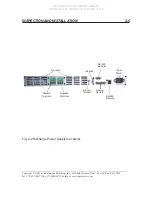
Figure 2-2 shows the back panel of the Discharge Power Supply. An RS-232
connection is provided on the back panel of this Power Supply for remote
operation. RS-232 connection at the back panel utilizes a DB-9 connector.
The RS-485 is for KRI autocontroller.
A ground stud is provided on the rear panel of this unit for grounding the
chassis of the Power Supply.
Analog connections, utilizing DB-25 female connectors, are provided on the
back panel of this controller for remote operation.
2.4 Installation
2.4.1 Mounting
The Power Supply is designed to be mounted in a standard 19-inch (483
mm) rack mount cabinet. The height of this Power Supply is 1.75 inches (45
mm) and the depth of the unit is approximately 21 inches (533 mm). When
installing the Discharge Power Supply into the cabinet refer to the Ion Source
Controller Manual for installation orientation relative to the other ion source
Power Supplies. Install the Power Supply in the rack mount cabinet prior to
making any electrical connections.
2.4.2 Cooling
This Power Supply is forced air cooled with the air
fl
ow entering and exiting
through the back panel of the chassis. Ensure that there are no obstructions
in the rack mount cabinet that will restrict the air
fl
ow.


