background image

OPERATION                                                                                      3-5

_______________________________________________________________________

Copyright © 2011 by Kaufman & Robinson, Inc., 1330 Blue Spruce Drive, Fort Collins, CO 80524
Tel: 970-495-0187, Fax: 970-484-9350, Internet: www.ionsources.com

DISCHARGE POWER SUPPLY MANUAL

MODEL DC3005, MODEL 30010, MODEL 15012

·

 SOURce:VOLTage or SOUR:VOLT Input the operating voltage.  The de-

sired operating voltage  in volts follow either the long or short form of the 

command.  A space can be inserted after the command, or the space can 

be omitted.  The level of voltage must be within the range for the power 

supply.  Up to three decimal places may be used to input the voltage, but 

these decimal places do not have to be speci

fi

 ed.  The decimal point is 

also not required if there are no signi

fi

 cant decimal places.  The discharge 

supply requires that both the SOURce:CURRent and SOURce:VOLTage 

be non zero to enable the power supply.  A current or voltage command of 

zero will put the discharge power supply into standby.

All the commands and queries must be followed by a carriage return.

NOTE:  If either VX command is zero the unit will go to standby. 

3.2.4 Operational sequence

Using a terminal program con

fi

 gured for the communications settings previ-

ously mentioned, input the following commands in the de

fi

 ned  sequence.  

User Inputs are shown with quotations to designate the exact command the 

user must input, the quotation marks should not be input into the terminal 

program.

• During power up of the Discharge Power Supply set the output to zero 

current output for safety. Input “VA0” then press the enter key.

• Determine the Discharge output current required.  Using the following 

formula, determine the decimal value required for input into the terminal 

program corresponding to the required Discharge current :

Input value = required discharge current = (0 to maximum amps) x 

4095/10.

Example:  A value of 5 amps of discharge current is desired.  Using the 

above formula, 5 X 4095/10 = 2047 for model DC30010.  

• Determine the Discharge output Voltage required.  Using the following 

formula, determine the decimal value required for input into the terminal 

program corresponding to the required Discharge voltage :

Input value = required discharge voltage = (0 to maximum volts) x 

4095/300.

Example:  A value of 200 volts of discharge voltage is desired. .  Using 

Summary of Contents for DC15012

Page 1: ...inson Inc 1330 Blue Spruce Drive Fort Collins Colorado 80524 Tel 970 495 0187 Fax 970 484 9350 Internet www ionsources com Copyright 2011 by Kaufman Robinson Inc All rights reserved No part of this publication may be reproduced without written permission June 2011 Version 1 ...

Page 2: ...CTION AND INSTALLATION 2 1 2 2 Inventory 2 1 2 3 Physical Description 2 1 2 3 1 Front Panel 2 1 2 3 2 Rear Panel 2 2 2 4 Installation 2 2 2 4 1 Mounting 2 2 2 4 2 Cooling 2 2 2 4 3 Electrical connections to ion source and discharge power supply 2 3 2 4 4 Electrical AC input 2 3 3 OPERATION 3 1 3 1 Local Mode 3 1 3 2 Remote Mode RS 232 3 2 3 2 1 Direct RS 232 connection from computer to discharge 3...

Page 3: ...www ionsources com DISCHARGE POWER SUPPLY MANUAL MODEL DC3005 MODEL 30010 MODEL 15012 Figures Fig 2 1 Discharge Power Supply front panel 2 4 Fig 2 2 Discharge Power Supply rear panel 2 5 Tables Table 1 1 Maximum Power Voltage and Output 1 3 Table 2 1 Inventory List 2 1 Table 3 4 Analog connections 3 7 Table 3 4 Interlock connections 3 9 Table 4 1 Help codes and error messages for the Discharge Pow...

Page 4: ...S485 High Speed Serial link for proprietary communications with KRI Controllers Fan on Demand cooling with thermal shutdown protection Front panel selectivity for local remote mode 1 2 Safety Caution Only technically qualified personnel should install maintain and troubleshoot the equipment described herein Lethal voltages and currents can be developed within the Power Supply therefore the Power S...

Page 5: ...ge for the Discharge Power Supply is 85 275 volts ac single phase at 50 60 Hz The maximum input current to the unit is electronically limited to 28 amps RMS Operation at lower line voltages may be limited by outlet capacity and or circuit breakers 1 3 4 DC Output The maximum output for the DC30010 model of this Power Supply is 300 VDC and 10 amps Operation at this level is limited by thermal prote...

Page 6: ...330 Blue Spruce Drive Fort Collins CO 80524 Tel 970 495 0187 Fax 970 484 9350 Internet www ionsources com DISCHARGE POWER SUPPLY MANUAL MODEL DC3005 MODEL 30010 MODEL 15012 Table 1 1 Maximum Power Voltage and Output Model Maximum Power Maximum Voltage Maximum Current 3005 1500 W 300 V 5 A 30010 2000 W 300 V 10 A 15015 2000 W 150 V 15 A ...

Page 7: ...any damage has occurred contact Kaufman Robinson Inc in addition to the ship ping company to report any damage see Warranty section 5 Retain packaging materials for shipment of the Power Supply Inventory the contents shipped to determine completeness of the order 2 2 Inventory The following items are shipped with each Power Supply Table 2 1 Inventory List Quantity Desciption Part Number 1 Discharg...

Page 8: ...Figure 2 2 shows the back panel of the Discharge Power Supply An RS 232 connection is provided on the back panel of this Power Supply for remote operation RS 232 connection at the back panel utilizes a DB 9 connector The RS 485 is for KRI autocontroller A ground stud is provided on the rear panel of this unit for grounding the chassis of the Power Supply Analog connections utilizing DB 25 female c...

Page 9: ...as purchased with an Ion Source and Fila ment Power Supply interconnecting cables are provided Information regard ing installation of these connecting cables can be found in the Ion Source Filament Cathode Version Controller Manual If the Discharge Power Supply was purchased as a stand alone unit contact Kaufman Robinson Inc for cabling requirements 2 4 4 Electrical AC input The Power Supply has b...

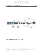
Page 10: ...______________ Copyright 2011 by Kaufman Robinson Inc 1330 Blue Spruce Drive Fort Collins CO 80524 Tel 970 495 0187 Fax 970 484 9350 Internet www ionsources com DISCHARGE POWER SUPPLY MANUAL MODEL DC3005 MODEL 30010 MODEL 15012 163 7 21 1 167 7 21 Fig 2 1 Discharge Power Supply front panel ...

Page 11: ...e Spruce Drive Fort Collins CO 80524 Tel 970 495 0187 Fax 970 484 9350 Internet www ionsources com DISCHARGE POWER SUPPLY MANUAL MODEL DC3005 MODEL 30010 MODEL 15012 163 7 21 1 167 7 21 Input Power RS 323 Remote RS 485 Remote Analog Remote Air vents Ground Terminal Positive Terminal Negative Terminal Interlock Fig 2 2 Discharge Power Supply rear panel ...

Page 12: ...upply will be in Standby with the Dis charge Amps and Volts Setpoints displayed The Setpoints that are displayed will be the last setpoints used before the supply was switched OFF If the last operation was with Remote control then the Power Supply will be in Remote when switched ON In this case the supply will respond to the remote commands in effect when switched ON Power Limit indicator Indicate...

Page 13: ...olts Discharge Amps display Displays the discharge current setpoint and run val ues in amps When the yellow setpoint indicator below the display is illuminated the setpoint value is displayed When the green run indicator is illuminated the run value is displayed Setpoint indicator Indicates when the setpoints are being displayed on the Digital Displays When the yellow setpoint indicator below the ...

Page 14: ... of methods Some type of terminal or communications program or programming can be used for controlling this unit Some examples of programs that can be used are Hyper Terminal provided with Microsoft Windows systems and LabviewTM by National InstrumentsTM Consult the user guide for installation and operation of the software that you plan on using for use of that program 3 2 2 Communications setting...

Page 15: ...f the unit is functioning normally or a number that corresponds to the front panel help codes as described in diagnostics section 4 MEASure CURRent or MEAS CURR Measure current query Returns the DC output current in amps with three decimal places MEASure VOLTage or MEAS VOLT Measure voltage query Returns the DC output voltage in volts with three decimal places SOURce CURRent or SOUR CURR Input the...

Page 16: ...ge return NOTE If either VX command is zero the unit will go to standby 3 2 4 Operational sequence Using a terminal program configured for the communications settings previ ously mentioned input the following commands in the defined sequence User Inputs are shown with quotations to designate the exact command the user must input the quotation marks should not be input into the terminal program Dur...

Page 17: ...ut VA0 then press the enter key The out put will drop to zero and the Standby LED will be illuminated Output Current Monitoring of the output current can be done using the following command Input RD0 then press the enter key This reads a decimal number from 0 4095 that can then be converted to the cor responding output current To convert the decimal number to the output current divide the returned...

Page 18: ... Supply for connection to the analog interface The pin descriptions for the interface are given below in table 1 There is a button on the front panel that can be used to switch from remote to local control There is also a two pin Molex connector on the back panel labeled INTERLOCK The pin descriptions for the interlock are also given below in table 3 4 1 Table 3 4 Analog connections Pin Number Des...

Page 19: ...on nected to common The shutdown is deactivated when 5 volts is applied or no contact is made Remote shutdown is indicated on the front panel when activated 15 Auxiliary 5 volts DC 200 mA max Also available at pin 13 and 25 16 Common 17 Common 18 Over Temperature Output A 5 volt output indicates over tem perature 5 kΩ source impedance 19 Discharge Voltage Monitor Outputs 0 to 5 volts for 0 to maxi...

Page 20: ...pruce Drive Fort Collins CO 80524 Tel 970 495 0187 Fax 970 484 9350 Internet www ionsources com DISCHARGE POWER SUPPLY MANUAL MODEL DC3005 MODEL 30010 MODEL 15012 Table 3 4 Interlock connections Pin Number Description 1 Active Low Interlock Connect to common Interlock pin 2 to enable the Discharge Power Supply 2 Interlock Return Common ...

Page 21: ...e gas bottle to the ion source Power must be removed from the Power Supplies prior to performing maintenance on the Ion Source 4 2 Diagnostic Table The following table may be used to assist in determining faults and corrective action for the Discharge Power Supply Table 4 1 Help codes and error messages for the Discharge Power Supply Help Code or Error Message Description Possible Causes and Corre...

Page 22: ...he PC Shows up only in re mote RS 232 operation Display says HLP 8 for 5 seconds Informational display only No action taken on unit operation Unit recovers from error condi tion if the problem goes away Make sure all of the equipment has adequate grounding Hot Thermal Overload Internal temperature in the power supply is too hot Power supply is in STANDBY Leave the power supply turned on until the ...

Page 23: ...nts KRI s obligation under this Limited Warranty is at KRI s option to repair or replace any defective equipment or parts of the equipment without charge to the purchas er which are returned shipping prepaid to the KRI facility 1306 Blue Spruce Unit A Fort Collins Colorado 80524 USA For return or repair of equipment purchaser must contact KRI for a Return Materials Authorization prior to shipment ...

Page 24: ...roblem encountered or the item to be returned Product Serial number Detailed description of problem Date of purchase Name and address of company Contact person If return to KRI is required you will be given an authorization number and instruct ed where to send it _______________________________________________________________________ Copyright 2011 by Kaufman Robinson Inc 1330 Blue Spruce Drive Fo...

Reviews: