INSPECTION AND INSTALLATION 2-1
_______________________________________________________________________
Copyright © 2011 by Kaufman & Robinson, Inc., 1330 Blue Spruce Drive, Fort Collins, CO 80524
Tel: 970-495-0187, Fax: 970-484-9350, Internet: www.ionsources.com
DISCHARGE POWER SUPPLY MANUAL
MODEL DC3005, MODEL 30010, MODEL 15012
2 INSPECTION AND INSTALLATION
This section describes how to install the Kaufman & Robinson, Inc., KRI® Dis-
charge Power Supply which has been designed for operation of a KRI Ion Source.
Unpacking and inspection, physical description, hardware inventories and installa-
tion information is provided to assist in facilitating a successful installation.
2.1 Unpacking and Inspection
Prior to shipment, the Power Supply was inspected and tested and has been
shipped free of defects. As soon as the Power Supply has been completely
removed from all packing materials a visual inspection should be made to de-
termine if there has been any damage to the products during shipment. If any
damage has occurred contact Kaufman & Robinson, Inc., in addition to the ship-
ping company to report any damage, see Warranty section 5. Retain packaging
materials for shipment of the Power Supply. Inventory the contents shipped to
determine completeness of the order.
2.2 Inventory
The following items are shipped with each Power Supply:
Table 2-1 Inventory List.
Quantity
Desciption
Part Number
1
Discharge Power Supply
DC30010/DC3005/
DC15012
1
Power Discharge Supply Cable
CBL-A07-PWR-HF-EH
1
Atmosphere Discharge Cable
CBL-A04-ATM-HF-EH
1
Discharge Power Supply Manual
2.3 Physical Description
2.3.1 Front Panel
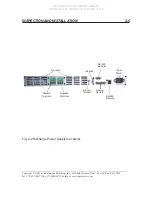
Figure 2-1 shows the front panel of this Power Supply. The Power Supply
has one power switch located on the front panel. The three white buttons
on the front panel are used for manual control of the power supply. The
button switch on the left allows the unit to be placed in an active (enabled)
or inactive (standby) mode. The front panel displays are still active in the
STANDBY mode. The middle button switch selects if the front panel (Local)
or rear panel (Remote) control of the VOLTAGE, and CURRENT. The rear
panel (Remote) includes both analog and RS-232 interface. The right button


