22
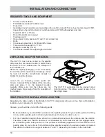
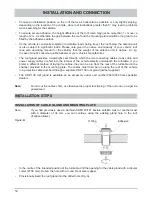
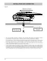
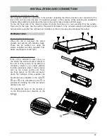
Using the adhesive strips supplied, now
install the infra-red sensor either on the
receiver or at the chosen location. If the
infra-red sensor is installed on the unit,
its cable can be threaded in at its base,
as for a phone, and routed to the rear of
the receiver (see diagram on the right).
When threading in the
cable, take care not to
damage its sheath.
INSTALLATION AND CONNECTION
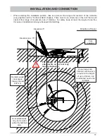
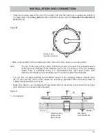
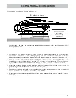
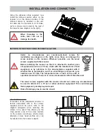
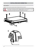
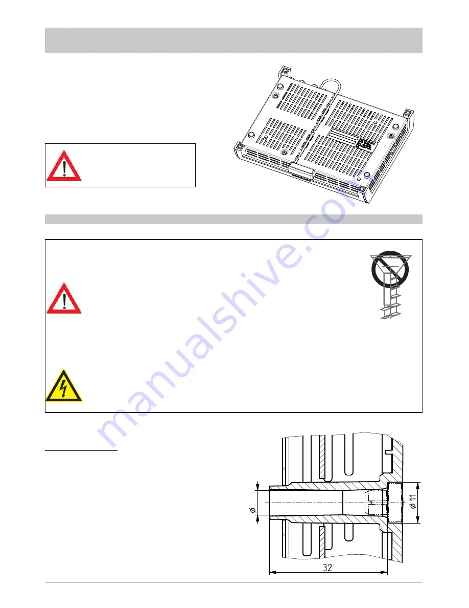
Use of other screws:
If because of the installation location or
factors associated with it, the screws
supplied cannot be used, refer to the
diagram alongside when selecting the
screws to be used. This shows you the
cross-section area of the screw sockets
on the receiver and shows which screws
(diameter, screw head pro
fi
les etc.) can
be inserted into the receiver support.
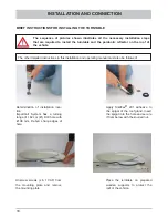
IMPORTANT INSTRUCTIONS FOR INSTALLATION
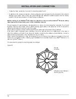
Under no circumstances use countersunk-head screws for
installation (see diagram on the right), since these can damage the
screw sockets on the receiver. Wherever possible, use the wood
screws supplied with the receiver.
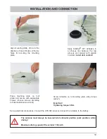
Before installing the receiver so that it is attached to another piece
of equipment (such as a TV set), check with the manufacturer of that
equipment or by reference to the documentation supplied with it
whether this is permissible, and if so what fi ttings (screws etc.) you
need/can use for this. The temperature rise of each of the units in
operation (receiver/TV set) can in some circumstances affect the other unit.
The wood screws supplied with the receiver should not under any circumstances
be used to attach it to a TV set or other electrical equipment! This could damage
that equipment, possibly beyond repair.
Risk of fatal injury due to electric shock!
6.6

