16
17
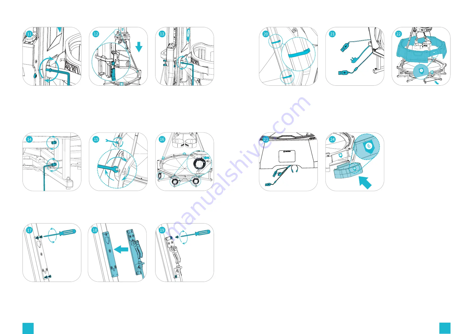
Unscrew the screws from
the back support.
Fasten the supporting rod
with the 2 velcro straps on
the rotation lock wire.
Insert the bolts of the back
support to the square holes
at the top of supporting
rods, and ensure that the
stickers "1" and "4" are
aligned.
Pull out the triple-end
cable with power cord and
2 USB cables. Connect
the extension cable to the
shorter of the two USB
cables.
Tighten the screws on each
side to the vertical tube at
the top of the supporting
rods.
Slowly place the shell
with the sticker "5" onto
the base, and make sure
that stickers "1" and "5"
are aligned.
Use the hex key/allen key to
tighten the four screws in
place on both sides, holding
the supporting rods firmly.
Securely tighten the bolt
joining the connecting wire
to the base frame.
Remove the three cables
tied to the base frame and
sort out the rotation lock
wire.
Unscrew the four screws
fastened on the plate of the
rotation lock and store
them for the future use.
Find the switch of the
rotation lock at the base
and put it together with the
plate on the supporting rod.
Tighten the four screws
removed earlier.
Connect the base housing
to the DC plug on the base
structure. The exposed two
USB cables and three-wire
power cables are inserted
into the bundle cable tube
Slide the safety step marked
with the sticker "6" into the
gap of the base frame.


