background image

New Unit Information 05.2007

Puzzi 8/1 C

Basic settings and service procedures


Page 17 / 29

Unit switch

1 Retaining screws (2x), bracket, switch

elements

2 Bracket, switch elements

3 Switch elements

4 Rubber covers

Replacing switches

If one of the switches (S1) or (S2) is defective,
it can be removed and replaced as follows.

– Remove the retaining screws (1).

– Remove switch elements bracket (2).

– Remove switch elements (3).

– Remove rubber covers (4).

(Procedure continued on Page 18)

Switch elements installed

Bracket removed

Switch elements removed

1

2

3

3

4

Summary of Contents for Puzzi 8/1 C

Page 1: ...New Unit Information New Unit Information 05 2007 Puzzi 8 1 C 1 100 200 0 5 906 335 0...

Page 2: ...shops offices etc Tank volume Fresh water tank 8 l Wastewater tank 7 l Noise emission 71 dB A Floor tool for carpets working width 230 mm Electrics Motor 1380 watt 7 5 m mains cable Bypass suction mo...

Page 3: ...g handle and suction tube storage during transport 3 Filler opening fresh water 4 Switch S2 water pump M2 5 Switch S1 suction motor M1 6 Unit housing upper section 9 2 3 5 7 10 11 12 1 8 4 7 Unit hous...

Page 4: ...Carrying handle and suction tube storage during transport 2 Mains cable retractor 3 Unit housing upper section 4 Bracket upholstery tool optional 7 1 2 4 6 8 3 5 5 Unit housing lower section 6 Bracket...

Page 5: ...Hook for transporting the suction hose 7 MAX mark maximum water level in the fresh water tank 8 Fresh water tank 1 2 3 4 6 8 7 9 10 11 12 13 14 17 5 15 16 5 9 Unit housing upper section 10 Bracket uph...

Page 6: ...Filters contaminations out of fresh water in order to prevent damage to the water pump M2 MAX mark The MAX mark 3 in the fresh water tank 2 indicates the maximum water quantity which may be added to...

Page 7: ...ions Page 7 29 1 Unit housing lower section 2 Air intake drawn in air opening with fluff strainer Unit housing wastewater tank removed 1 2 Fluff strainer Filterscoarsecontaminationsoutofthedrawnin air...

Page 8: ...05 2007 Unit functions Puzzi 8 1 C Page 8 29 Unit housing upper section removed 1 Unit housing upper section 2 Sealing strip 3 Switch S2 water pump M2 4 Switch S1 suction motor M1 5 Unit housing lowe...

Page 9: ...29 View from below 1 Fresh water hose to the spray suction hose 2 Floor cover 3 Wheel LH 4 Retaining screw LH wheel 7 9 6 5 5 1 2 3 4 5 Air discharge motor cooling air 6 Retaining screw RH wheel 7 Wh...

Page 10: ...uction tube 2 Carrying handle and suction tube storage during transport 3 Hook for transporting the suction hose 4 Spray suction hose 3 3 The spray suction tube is pressed onto the carrying handle 2 f...

Page 11: ...witch S1 suction motor M1 4 Terminal strip X7 switch S1 suction motor M1 5 Terminal strip X8 suction motor M1 6 Terminal strip X6 suction motor M1 7 Terminal strip X12 mains connection to switch S1 su...

Page 12: ...Page 12 29 1 Spray suction hose 2 Fresh water hose 3 Connection sleeve suction hose 4 Connection fresh water hose 5 Handle section 6 Lever spray function release 7 Threaded connection connection to t...

Page 13: ...suction tube 1 2 1 3 4 Threaded connection closed Threaded connection open Floor tool for carpets Threaded connection The threaded connection 2 is used to connect the handle section see Page 12 Item 5...

Page 14: ...ray nozzle 2 Guide handle Guide handle 1 Spray nozzle The spray nozzle 1 sprays the fresh water cleaning agent mixture onto the carpet to be cleaned Guide handle The guide handle 2 can be used to exer...

Page 15: ...New Unit Information 05 2007 Puzzi 8 1 C Circuit diagram Page 15 29 Circuit diagram 0 088 980 0...

Page 16: ...iagram Puzzi 8 1 C Page 16 29 Circuit diagram 0 088 980 0 C1 Capacitor F1 Fuse in Japan version only M1 Suction motor M2 Water pump N1 Printed circuit board S1 ON OFF switch suction motor S2 ON OFF sw...

Page 17: ...lements 3 Switch elements 4 Rubber covers Replacing switches If one of the switches S1 or S2 is defective it can be removed and replaced as follows Remove the retaining screws 1 Remove switch elements...

Page 18: ...covers removed Switches S1 and S2 pulled out 1 Switch S2 water pump M2 2 Switch S1 suction motor M1 Replacing switches Pulltherelevantswitch 1 2 outofthebracket Remove the cable connections from the...

Page 19: ...Air duct drawn in air from floor tool 8 Air intake opening with fluff strainer 9 Fresh water hose to the spray suction hose 10 Hose clamp 11 Water pump M2 12 Water hose from fresh water tank 13 Retai...

Page 20: ...or M1 4 Rubber ring 5 Holder suction motor 6 Printed circuit board N1 7 Fresh water hose to the spray suction hose 8 Water pump M2 9 Water hose from fresh water tank 10 Mains cable 11 Retaining screws...

Page 21: ...21 29 Suction motor 1 Holder suction motor 2 Carbon brushes 3 Retaining screws carbon brushes 4 Cable connection suction motor 5 Suction motor M1 1 3 2 3 2 4 5 Replacing the carbon brushes Remove the...

Page 22: ...water pump 2 with the rubber mounts 1 from the holder 5 Remove hose clamp 3 Pull hoses 4 6 off the water pump 2 Removerubbermount 1 fromthewaterpump Install new water pump in reverse order 1 Rubber m...

Page 23: ...e procedures Page 23 29 Wheel 1 Wheel installed 2 Retaining screw wheel 3 Holder wheel 5 4 1 2 1 Wheel installed Wheel retaining screw removed Replacing the wheel Remove the retaining screw 2 Pull the...

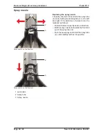
Page 24: ...ay tube 2 and is held by two latching tabs 1 on the left and right If it is defective or blocked it can be replaced as follows Pushlatchtabs 1 apart seearrowdirection Pull the spray nozzle 3 towards t...

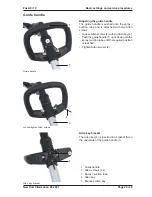
Page 25: ...wo Allen screws Loosen Allen screws 2 with an Allen key 4 Push the guide handle 1 up or down onto the spray suction tube until the required position is reached Tighten Allen screws 2 4 4 3 3 Allen key...

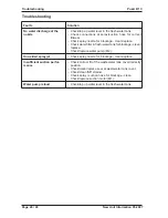
Page 26: ...lace Check water filter in fresh water tank for blockage clean replace Check replace water pump M2 One sided spray jet Check spray nozzle for blockage clean replace Insufficient suction perfor mance C...

Page 27: ...he next issue of the spare parts CD ROM DISIS and are also available in kaercher inside https kaercher inside com Special tools No special tools are required Tightening torque No details Technical spe...

Page 28: ...Cover suction motor 19 Cover wastewater tank 3 D Diode 16 E Electrics 2 F Filler opening fresh water 3 Floor cover 9 Floor cover removed 19 Floor tool for carpets working width 230 mm 13 Fluff strain...

Page 29: ...castor 3 T Technical specifications 27 Terminal strip X1 switch S2 water pump M2 11 Terminal strip X10 mains connection 11 Terminal strip X11 mains connection 11 Terminal strip X12 mains connection w...

Reviews: