background image


English 

5.906-472.0 Rev. 00 (08/08)

 11

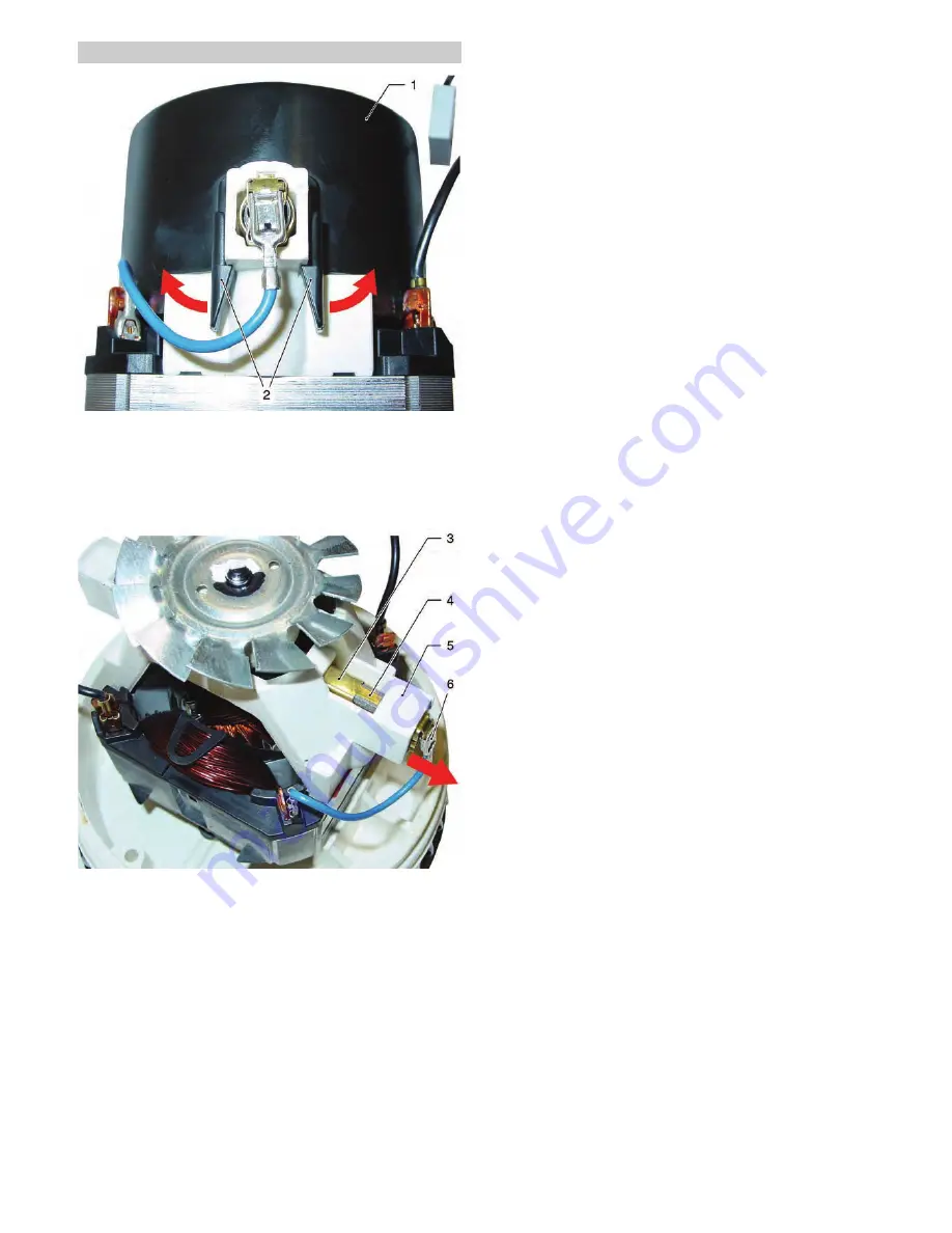
If the abrasive coals on the suction turbine (M1) are worn, they can 
be replaced as follows.

Î

Press the locking noses (2) on both sides of the cover (1) slight-
ly toward the outside and remove the cover (1) toward the top. 

Î

Pull off the connector plug (6).

Î

Press the safety flag (4) down and pull the abrasive coal (3) out 
of the abrasive coal chute (5).

Î

Install the new abrasive coal in reverse order.

Note

After inserting the new abrasive coal into the abrasive coal chute, 
the safety flag must be bent slightly toward the top. This secures 
the abrasive coal from inadvertently slipping out of the abrasive 
coal chute.

1

Cover

2

Locking noses (4x)

3

Abrasive coal (2x)

4

Safety flag

5

Abrasive coal chute

6

Connection plug

5.7

Replacing the abrasive coals of the suction turbine

Summary of Contents for NT 27/1

Page 1: ...English 5 906 472 0 Rev 00 08 08 1 NT 27 1 Advanced NT 27 1 Me Me Advanced NT 48 1 Service Manual ...

Page 2: ...n head removed 6 4 4 Dirt water drain hose on the NT 48 1 6 5 Basic settings and service procedures 7 5 1 Remove cartridge filter 7 5 2 Replace seal 7 5 3 Remove the swimmer 7 5 4 Separate the suction turbine casing from the suction head casing 8 5 5 Replace appliance switch 8 5 6 Replacing the suction turbine 9 5 7 Replacing the abrasive coals of the suction turbine 11 6 Circuit diagram 12 6 1 Ci...

Page 3: ...e is meant for dry and wet cleaning of floors and walls This appliance is suited for the commercial use e g in hotels schools hospitals factories shops offices and rental compa nies Storage compartments for tools on the suction head Container capacity NT 27 1 27 Liter NT 48 1 48 Liter Clip system for rapid change or connection of accessories Chassis NT 27 1 five swivel casters NT 48 1 two swivel c...

Page 4: ... for tools 7 Lock for suction head 2x as of July 2008 8 Lock for suction head 2x 9 Accessory mount 10 Dirt receptacle 11 Swivel casters 5x 12 Floor nozzle 13 Suction tubes 2 x 0 5 m 14 Bayonet connector at suction hose 15 Suction hose connection 16 Suction head 17 Appliance switch S1 4 Parts of the system 4 1 View of NT 27 1 ...

Page 5: ...08 5 Intake for dirt water drain hose 6 Lock for suction head 2x 7 Dirt water drain hose 8 Dirt receptacle 9 Accessory mount 10 Impeller 2x 11 Guiding roll with fixed position brake 12 Steering roller 13 Suction hose 14 Bayonet connector at suction hose 15 Suction hose connection 16 Suction head 17 Appliance switch S1 4 2 View of NT 48 1 ...

Page 6: ...48 1 is equipped with a dirt water drain hose 2 The dirt water can be drained from the dirt container into a drain chute via this dirt water drain hose Î Pull the dirt water drain hose 2 off of the intake 1 and place it into a drain chute Î Let the dirt water drain completely Î After emptying reinsert the dirt water drain hose 2 into the in take 1 1 Intake for dirt water drain hose 2 Dirt water dr...

Page 7: ...d and insert new seal Remove the swimmer as follows to clean it Î Remove the cartridge filter see chapter 5 1 Î Remove the fastening screws 3 Î Remove the swimmer casing 1 Î Remove the swimmer 2 from the swimmer casing The swim mer can now be cleaned or replaced if necessary Note When installing the swimmer 2 make sure that the open side of the swimmer is located inside the swimmer casing If the s...

Page 8: ... be replaced as fol lows Î Separate the suction turbine casing from the suction head cas ing see Chapt 5 4 Î Pull the appliance switch 3 out of the holder 7 Î Pull all four connector plugs 5 6 off of the appliance switch 3 Î Install the new appliance switch in reverse order Note When installing the appliance switch make sure that all connecting cables are routed in their respective cable guides ar...

Page 9: ...ction turbine casing from the suction head cas ing see Chapt 5 4 Î Pull the appliance switch 3 out of the holder 4 Î Pull the connecting cable 2 of the suction turbine 6 off of the appliance switch 3 Î Pull the connecting cable of the suction turbine out of the cable slots arrows Î Remove the cover 5 from the suction turbine casing Î Remove the fastening screws 8 of the suction channel cover 7 Î R...

Page 10: ...e suction channel cover 7 has a semi circular recess on its edge There is a semi circular stop in the suction turbine casing Î Place the suction channel cover 7 on the suction turbine cas ing so that the semi circular stop of the suction turbine casing rests in the semi circular recess of the suction channel cover 7 1 Insulation 2 Connecting cable suction turbine M1 3 Appliance switch S1 4 Bracket...

Page 11: ...ety flag 4 down and pull the abrasive coal 3 out of the abrasive coal chute 5 Î Install the new abrasive coal in reverse order Note After inserting the new abrasive coal into the abrasive coal chute the safety flag must be bent slightly toward the top This secures the abrasive coal from inadvertently slipping out of the abrasive coal chute 1 Cover 2 Locking noses 4x 3 Abrasive coal 2x 4 Safety fla...

Page 12: ...12 English 5 906 472 0 Rev 00 08 08 6 Circuit diagram 6 1 Circuit diagram 0 088 563 0 C1 De interference capacitor M1 Suction turbine S1 Power switch X1 Mains plug X2 Socket TE version only ...

Page 13: ...osed properly close properly Check the suction nozzle the suction pipe suction hose and cartridge filter for ob structions clear if necessary Exchange the paper filter bag Check suction system to see if there are any leaks repair leaks Cartridge filter is defective replace Dust comes out during the vacuum ing Dirt container or paper filter bag full empty or replace paper filter bag Check the corre...

Reviews: