10
English
5.906-472.0 Rev. 00 (08/08)
Î
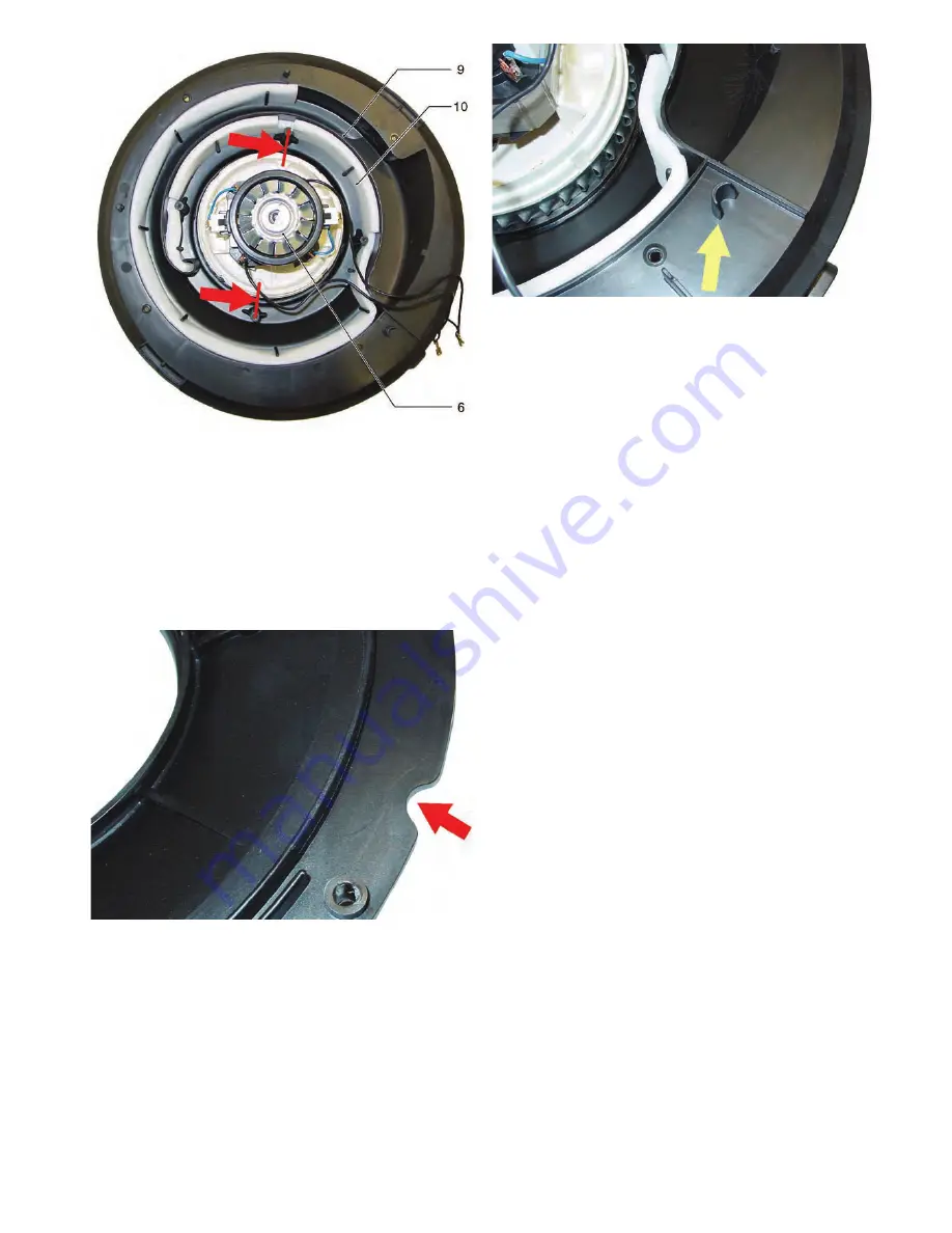
The suction turbine (6) can be removed for cleaning or replace-
ment.
Note
When installing the suction turbine, watch for correct placement.
The protrusions on the suction turbine must be aligned with the
screw heads (see arrows).
Observe the following when installing the suction channel
cover (7):
The suction channel cover (7) has a semi-circular recess on its
edge.
There is a semi-circular stop in the suction turbine casing.
Î
Place the suction channel cover (7) on the suction turbine cas-
ing, so that the semi-circular stop of the suction turbine casing
rests in the semi-circular recess of the suction channel cover
(7).
1
Insulation
2
Connecting cable, suction turbine (M1)
3
Appliance switch (S1)
4
Bracket
5
Cover
6
Suction turbine (M1)
7
Suction channel cover
8
Fastening screws (4x), suction channel cover
9
Suction channel
10 Insulation


