11
NC/J
series
【
7
】
PRESSER FOOT
7-1 Adjusting presser foot pressure
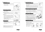
The presser foot pressure should be as light as
possible, yet be sufficient to feed the fabric and
produce uniform stitches.
To increase the presser foot pressure, turn the
adjusting knob clockwise.
On the NC/J series machine is available two presser
foot independently, one of “A” which press fabric that
the presser are adjusted by loosen nut D and turn
screw C clockwise to give more presser. Another one
of side roller “E” which press the tree-ply that the
presser are adjusted by loosen nut H and turn screw
G clockwise to give more presser. Standard
adjustment of both their presser is height of C is
57mm and G is 32mm.
7-2 Presser foot lift (NC/J series)
The presser foot ”A” is synchronized up and down
of it with side roller ”E”. The adjustment of amount
of it by loosen screw K and adjust the connecting
plate J up and down. The presser foot should be
7.5mm above the top surface of the guide plate.
12
NC/J
series
7-3 Position of the presser foot & foot lift
(
NC/SJ series
)
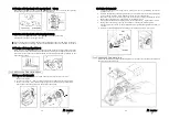
Fit the presser foot onto the presser bar so that the
needle can drop correctly to the center of the presser
foot needle drop hole.
■
Position of the presser foot
Loosen screw A. Adjust by moving the presser foot
left or right while checking to make sure the needle
drops correctly to the center of the presser foot needle
drop hole.
■
Foot lift
The presser foot should be 9mm above the top
surface of the needle plate.
Set the stopper B at the required position. Fasten the
presser foot lift lever with nut C so that the lever
cannot be lowered. Please adjust if the clearance
between top of the needle plate and bottom of the foot
is required, loosen nut E and move down the screw D.
【
8
】
SIDE ROLLER ADJUSTMENT
(
NC/J series
)
8-1 Roller position of front-back
To adjust the side roller position of front-back is
slide on the bracket C by loosen screw B. The
standard position is almost same line with a part of
rise up of presser foot where position in bottom of it’s
stroke and a part of the side roller as right illustration
A and G. Also align with outer circumference of roller
shaft D and center of needle F. (see right illustration
E)
Summary of Contents for NC Series
Page 2: ......
Page 3: ......
Page 4: ......
Page 5: ......
Page 6: ......
Page 7: ......
Page 8: ......
Page 9: ......
Page 10: ......
Page 11: ......
Page 12: ......
Page 13: ......
Page 14: ......
Page 15: ......
Page 16: ......
Page 17: ......
Page 18: ......
Page 19: ......
Page 20: ......
Page 21: ......
Page 22: ......
Page 23: ......
Page 24: ......
Page 25: ......
Page 26: ......
Page 27: ......
Page 28: ......
Page 29: ......
Page 30: ......
Page 31: ......
Page 32: ......
Page 33: ......
Page 34: ......
Page 35: ......
Page 36: ......
Page 37: ......
Page 38: ......
Page 39: ......
Page 40: ......
Page 41: ......
Page 42: ......
Page 43: ......
Page 44: ......
Page 45: ......
Page 46: ......
Page 47: ......
Page 48: ......
Page 51: ...NC Series Instruction Manual NC1103 4 G series ...
Page 63: ...NC J SJ Series Instruction Manual NC1001GSJ NC1001GSJF NC1001GJ ...


