6
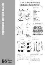
DIESEL GENERATOR OVERVIEW,
CONFIGURATION, COMPONENTS
Fig. 1
1. Reinforced frame
2. Fuel tank
3. Air filter
4. Antivibration mounts
5. Fuel filter
6. Oil filter
7. Oil dipstick
8. Oil drain hole
9. Engine safety switch
10. Battery
11. Control panel
12. Soundproof housing
13. Wheels
The manufacturer
reserves the right to make
changes in the product
design, configuration and
construction. The images in
this manual are for reference
only and may differ from
the actual components and
inscriptions on the products.
1. Generator
2. Packaging
3. Owner’s manual
4. Optional equipment:
Complete set:
1. Oil filter key;
2. 230V plug. 16 A/ (2Р+РЕ);
3. 230V plug. 32А (2P+E);
4. 230V plug. 63 А (3P+E+N) - for models:
14100HDE ATSR, 14200HDES ATSR;
5. 400V plug. 16А (3P+E+N) - for models:
KS 14100HDE1/3 ATSR, KS 14200HDES 1/3
ATSR;
6. 400V plug. 32 А (3P+N+PE) - for models:
KS 14100HDE 1/3 ATSR, KS 14200HDES 1/3
ATSR;
7. 2x ignition keys;
8. 10х12 mm open end wrench;
9. 13х16 mm open end wrench;
10. 14х17 mm open end wrench;
11. 6.0 mm РН2 offset screwdriver.
11
10
4
2
1
2
11
9
1
13
12
5, 10
3, 6, 7, 8
13
3
5, 6, 7, 8
Fig. 2
2
7
3
5
6
4
8
9
10
11
1
IMPORTANT!
Summary of Contents for KS 14100HDE ATSR
Page 31: ......


