Nesis III — Installation Manual
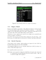
14.1
Fuel Level Sensors
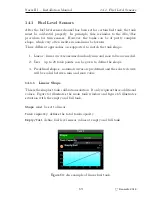
Figure 65:
An example of linear fuel tank.
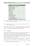
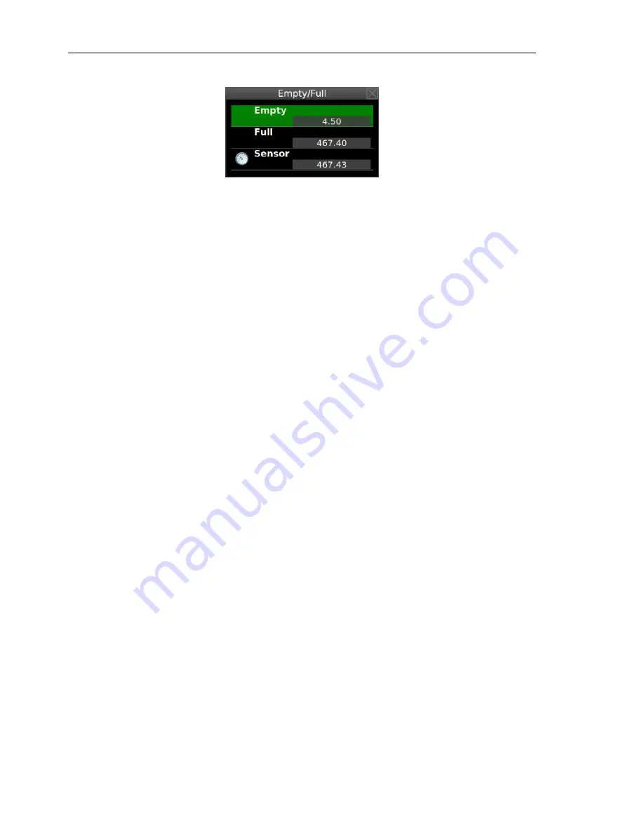
Typically, the tank is completely drained and a value shown by the fuel level
sensor is copied to the
Empty
. Then, the tank is filled with fuel and the sensor
value is copied to the
Full
.
We recommend taking notes. If something goes wrong, the empty and full
values can be entered directly (from notes) - without messing with a fuel
again.
14.1.2
User Shape
This is the most complex solution, but also the most precise one. It allows
up to 20 calibration points per tank.
20 points is an overkill, 5-8 points
is usually more than enough. Fuel level sensors precision is usually pretty
limited, sometimes also fuel dependent and having too much points is not
beneficial.
In order to define a user shape for tank, set the
Shape
parameter to
User
.
The window will change slightly. Then select the
Edit
item. This opens a
window, where tank measurements are manipulated.
A typical procedure is described next. Taking notes on paper is highly rec-
ommended.
1. Make sure that aircraft is in level position for a cruise flight.
2. Make the tank empty – drain all fuel out. Select proper fuel sensor (or
tank) and set
User
shape. Select the
Edit
item and issue the
Clear
com-
mand to remove any existing points. Figure 66a shows the situation.
There are no points in the
Measurements
list.
Sensor
value is informa-
tive and shows the readings from the sensor. This value is either voltage
or resistance detected by Daqu – this depends on the sensor type.
3. Slowly pour some fuel into the tank and observe when the
Sensor
value
starts changing. Usually sensors will not react immediately, as they
70
©
Kanardia
2018


