Nesis III — Installation Manual
14.1
Fuel Level Sensors
14.1
Fuel Level Sensors
After the fuel level sensor channel has been set for certain fuel tank, the tank
must be calibrated properly. In principle, this is similar to the
Min/Max
procedure for trim sensors. However, the tanks can be of pretty complex
shape, which very often results in non-linear behaviour.
Three different approaches are supported to match the tank shape:
1. Linear – linear curve is assumed and only min and max value are needed.
2. User – up to 20 tank points can be given to define the shape.
3. Predefined shapes – nominal curves are predefined and the selected curve
will be scaled between min and max value.
14.1.1
Linear Shape
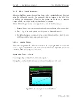
This is the simplest tank calibration solution. It only requires three additional
values. Figure 64 illustrates the main tank window and figure 65 illustrates
situation with the empty and full tank.
Shape
must be set to linear.
Tank capacity
defines the total tank capacity.
Empty/full
define fuel level sensor values at empty and full tank.
Figure 64:
An example of linear fuel tank.
69
©
Kanardia
2018








![Navig[8]r NAVBIKE-GPS User Manual preview](http://thumbs.mh-extra.com/thumbs/navig-8-r/navbike-gps/navbike-gps_user-manual_3574097-01.webp)
