Nesis III — Installation Manual
2.3
The Cutout
23.4
16.9
30
41.3
E
xt
ra
s
pa
ce
fo
r
ca
bl
es
a
nd
t
u
bi
ng
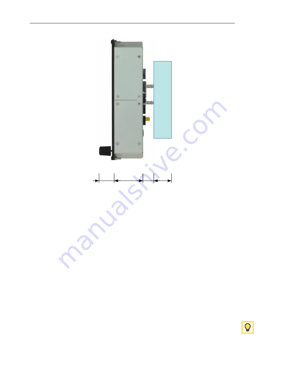
Figure 1:
Nesis side view with dimensions.
cutout tolerance was already added to the green cutout line. Figure 4 illus-
trates the cutout dimension.
Some mounting notes:
The display is mounted from front.
The display is shipped with a set of mounting hardware (four screws and
nuts). You can replace screws and nuts with more appropriate ones, Do
not use screws with head larger than 5.5 mm in diameter.
Do not re-drill holes in the bezel.
Due to highly sensitive multi point touch screen, the bezel had to be
made of non-conductive material – it is made of ABS plastic. Please
be careful. Do not bend the bezel and do not over-tighten the screws.
Bezel corners are especially sensitive.
Print the template on a hard paper. After printing, take a precise ruler or
measuring tape and make sure that printed sizes are correct. This procedure
12
©
Kanardia
2018


