Luftreiniger KA-520
Assembly instructions
5
3
Transport, storage and packaging
3.1
General transport instructions
Check on delivery for completeness and transport damage.
Proceed as follows in the event of visible damage:
Do not accept delivery or only accept with reservations.
Record any transport damage on the transportation documents or on the transport company's
delivery note.
Submit a complaint to the freight forwarder.
IMPORTANT NOTE!
Warranty claims can only be made within the applicable period for complaints.
(More information is available in the
4
Installation and wiring
IMPORTANT NOTE!
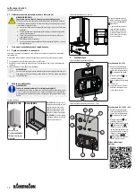
Ensure that the unit is horizontal and maintain minimum clearances!
Only position the unit on a horizontal, stable base surface with a minimum clear-
ance of 15 cm to the rear and to the wall at the side! Leave 50 cm clear in front
of the air inlet and outlet to guarantee optimum operation of the unit.
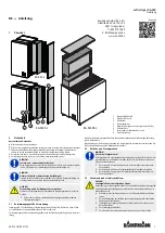
Position of the unit
Position standing
KA-520 L / XL
KA-520 XXL
Bond the felt glider
on site!
KA-520 L / XL:
The air purifier
can be used standing upright or
lying horizontally. Attach the
felt gliders supplied to the un-
derside of the unit to prevent
damage to the floor!
KA-520 XXL:
The adjustment
feet supplied must be screwed
into the underside of the unit!
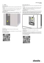
Adhering floor castors to the underside of the unit
max.
1
Attach floor castors pre-as-
sembled on metal plates
1
(accessory) to the underside of
the unit.
Remove the protective film
from the adhesive strips and
press the plates onto the un-
derside of the unit as shown
in the figure.
5
Commissioning
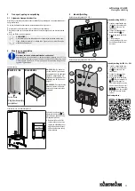
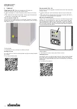
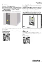
Electrical connection area of KA-520 L
1
2
3
Commissioning the KA-520
L
Insert the connection cable
supplied into the mains
socket
3
, then into the
power socket.
Use the main switch
2
to
switch on the unit.
Select the required operating
level
1
:
I: low power
II: high power, e.g. for tem-
porary flushing of the room
Electrical connection area of KA-520
XL + XXL
6
8
7
5
3
4
2
1
Commissioning the KA-520
XL + XXL
Insert the connection cable
supplied into the mains
socket
1
, then into the
power socket.
Use the main switch
2
to
switch on the unit.
Select the required operating
stage I
4
(low power) or II
3
(high power, e.g. for
temporary flushing of the
room): Refer to the adhesive
label on the back for further
information on the status
lights
5
6
7
and timer
operation
8
.
Operation video:
Summary of Contents for KA-520 L
Page 16: ...16...

