35
OODMANUAL 0720
KAM CONTROLS, INC.
RS232 COMMUNICATION
If you have not already done so, follow the previous procedures of the Troubleshooting section to verify power
supplies and check the 4-20 mA output.
Before proceeding, please ensure that RealTerm has been installed and properly configured as per instructions on
pages 20-22 of this manual. Also, please verify the driver for the supplied USB to serial converter is installed on
your PC.
1.
Using a multimeter in voltmeter mode, measure the voltage between the terminals RS232 TXD and GND. Ensure
the terminal screws on the board are fully closed. The voltage should be between -5 and -10 VDC. If the voltage
is not between the stated range, then the RS232 communication circuit might be damaged. Please contact KAM
Technical Support for further assistance.
2.
If the voltage is within the stated range, proceed to connect the supplied RS232 serial cable and USB to serial
converter to your computer and launch RealTerm.
T R O U B L E S H O O T I N G C O N T I N U E D
3.
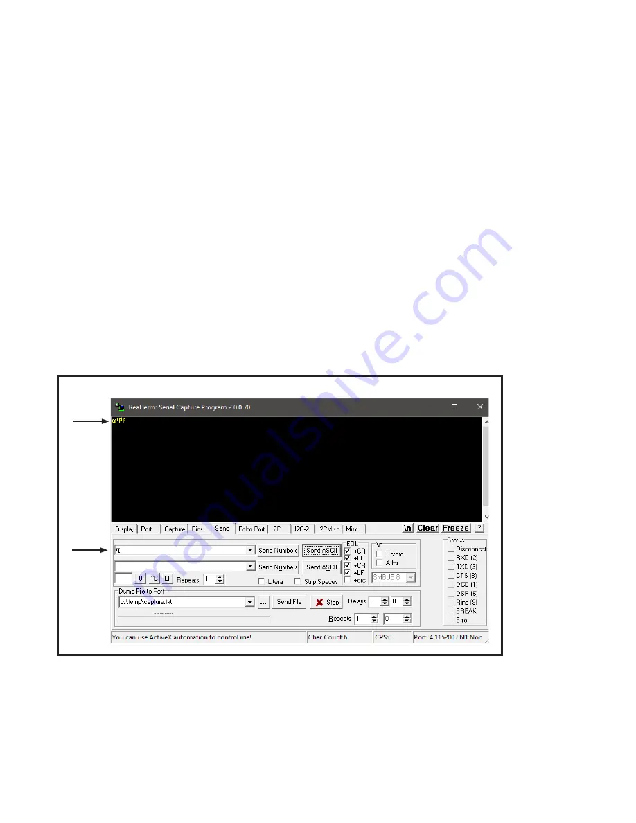
The RS232 serial cable has three wires (red, white, and black). Connect the tips of the white wire (RS232 RX)
and the red wire (RS232 TX) together. While these wires are connected, type any letter (e.g. "q") in any of the
command boxes of the “Send” tab on RealTerm and click on “Send ASCII." If the configuration is done properly,
the letter will appear in the window display. FIG. 6-2.
FIG. 6-2
If there is no response, verify the RealTerm settings as per the instructions on pages 20-22 of this manual and try
sending the command again.
If there is no change, use another RS232 serial cable and/or USB to serial converter and try sending the command
once more.
If there is still no change, there might be a communication issue with the RS232 serial cable, the USB to serial
converter, or the computer. Please contact KAM Technical Support for further assistance.


