3 Description and Operation
24
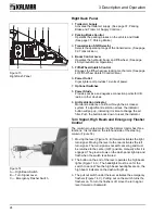
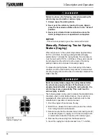
Right Dash Panel
1.
Trailer Air Supply
Activates the trailer air supply. (See page 37, Parking
Brake and Trailer Air Supply Controls.)
2.
Parking Brake Control
Operates the parking brakes on the vehicle and trailer.
(See page 37, Parking Brake.)
3.
Transmission Shift Selector
Selects the operating range of the transmission. (See page
32, Transmission.)
4.
Boom Control Lever
Operates the hydraulic boom and fifth wheel. (See page
40, Hydraulic Boom Operation.)
5.
Fifth Wheel Unlatch Control
Engages the fifth wheel jaw locking mechanism. (See page
40, Fifth Wheel Unlatch Control Valve.)
6.
Power Outlet
Cigar lighter port provides 12-volts of power.
7.
Optional Switches
8.
Power Studs
Provides positive and negative connection points for CB
radio or other devices.
9.
Air Restriction Indicator
Monitors resistance of airflow through the air cleaner
system. If a significant restriction arises, the indicator
button will pop up, indicating it is time to change the air
filter. Push the button back down to reset the indicator.
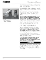
Turn Signal, High Beam and Emergency Flasher
Control
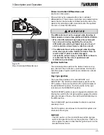
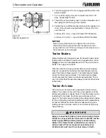
The column-mounted control on the Kalmar tractor has three
functions. It is located on the left-hand side of the steering
column (Figure 14).
1. Moving the lever (Figure 14, B) forward activates the right
turn signal. Moving the lever to the rear activates the left
turn signal. The turn signal is not self canceling and must
be returned to the center (OFF) position manually after it is
engaged. The green arrows on the dash panel light up and
flash when the switch is activated.
2. The button on the end of the lever operates the high beam
lights (Figure 14, A). The headlights must be on for the
switch to work. When the high beam headlights are on, the
high beam indicator on the dash will light up.
3. The pull out switch under the lever activates the emergency
flashers (Figure 14, C). Pulling out on the switch turns the
flashers on. To turn the flashers off, move the turn signal
lever forward or backward.
Figure 13
Right Dash Panel
8
1
3
4
9
5
7
6
2
Figure 14
A — High Beam Switch
B — Turn Signal Lever
C — Emergency Flasher Switch

