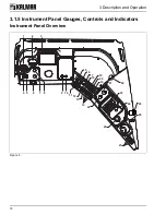
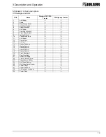
3 Description and Operation
20
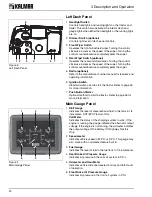
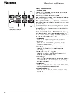
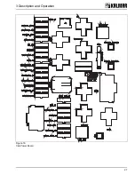
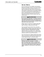
Left Dash Panel
1.
Headlight Switch
Controls headlights and running lights on the tractor and
trailer. This switch also activates the interior dash and
gauge lights when either the headlights or the running lights
are on.
2.
Dimmer Switch (optional)
Controls light level of dash panel controls.
3.
Front Wiper Switch
Operates the front windshield wiper. Turning the control
clockwise increases the speed of the wiper. Turning the
control counterclockwise completely parks the wiper.
4.
Rear Wiper Switch (optional)
Operates the rear windshield wiper. Turning the control
clockwise increases the speed of the wiper. Turning the
control counterclockwise completely parks the wiper.
5.
Radio (optional)
Refer to the manufacturer's owner manual for features and
operating information.
6.
Ignition Switch
Standard switch used to start the tractor. Refer to page 25
for more information.
7.
Push Button Starter
Optional method to start the tractor. Refer to page 26 for
more information.
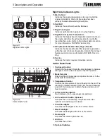
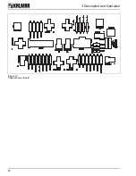
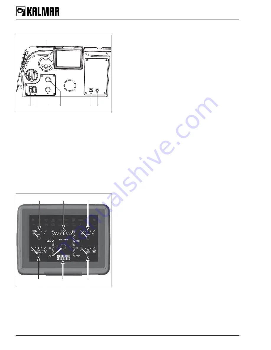
Main Gauge Panel
1.
DEF Gauge
Indicates the level of diesel exhaust fluid in the tank in 1/4
increments. DOT/EPA Tractors Only.
Volt Meter
Indicates the status of the charging system in volts. If the
engine is running, the gauge indicates the alternator output
voltage. If the engine is not running, the voltmeter indicates
the output voltage of the battery. Off-Highway Tractors
Only.
2.
Speedometer
Indicates vehicle speed in M.P.H. or K.P.H. This gauge may
also come with an odometer feature built in.
3.
Fuel Gauge
Indicates the level of fuel in the fuel tank in 1/4 increments.
4.
Rear Brake Air Pressure Gauge
Indicates air pressure in the rear air system in P.S.I.
5.
Odometer and Hour Meter
Indicates vehicle distance traveled in miles and total hours
of operation.
6.
Front Brake Air Pressure Gauge
Indicates air pressure in the front air system in P.S.I.
Figure 6
Left Dash Panel
1
5
2
6
4
7
3
Figure 7
Main Gauge Panel
1
2
3
6
5
4


