background image

Optidew User’s Manual

24


October 2019

OPERATION

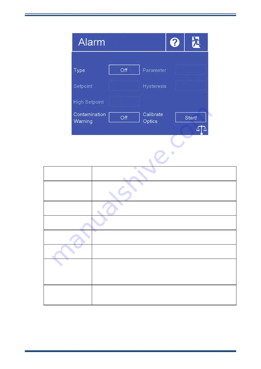
Alarm

Figure 18 

Alarm screen

Type

Sets the trip criteria for the process alarm

Available input:

 Over, Under, In. Band, Out. Band, Off

Parameter

Sets the parameter associated with the process alarm

Available input:

 DP, Temperature, Pressure, %RH, wvp, g/m

3

g/kg, ppm

V

, ppmW, Wet Bulb

Setpoint 

Sets the trip point for Over or Under alarm types

Available input:

 Depending on parameter

Low Setpoint

Sets the low trip point for Band alarm types

Available input:

 Depending on parameter

High Setpoint

Sets the high trip point for Band alarm types

Available input:

 Depending on parameter

Hysteresis

Sets the deviation from trip point before the alarm deactivates

Available input:

 Depending on parameter

Contamination 

Warning

Sets whether an Optics Warning trips the process alarm.

Refer to sections 4.6 and 5.2 for information about the optics 

warning.

Available input:

 On, Off

Calibrate Optics

It is necessary to run this function whenever the mirror is 

cleaned, or if a different dewpoint sensor is installed. Following 

this, a DCC will begin.

Summary of Contents for Optidew Bench Top

Page 1: ...October 2019 This document is the property of Kahn Instruments and may not either in part or whole be copied or otherwise reproduced communicated in any way to third parties nor stored in any data pro...

Page 2: ...Optidew For Kahn Instruments contact information please go to www kahn com...

Page 3: ...Installation 13 2 4 1 Environmental monitoring 13 2 4 2 Sample flow monitoring 13 2 4 3 Integral Sensor mounting 14 2 5 Temperature Probe Installation 14 2 6 Pressure Transmitter Installation 14 3 USE...

Page 4: ...e 32 4 3 1 Sampling Hints 32 4 3 2 First Time Operation 35 4 4 Operational Functions 35 4 4 1 DCC Function 35 4 4 2 MAXCOOL Function 36 4 4 3 Frost Assurance Technology FAST 36 4 4 4 STANDBY Mode 36 4...

Page 5: ...Figure 11 Analog output connector 11 Figure 12 Relay contact connector 11 Figure 13 Main screen 15 Figure 14 Main screen layout 16 Figure 15 DCC menu 21 Figure 16 Logging screen 22 Figure 17 Outputs s...

Page 6: ...Optidew User s Manual vi October 2019 Appendices Appendix A Technical Specifications 44 Appendix B Modbus Register Map 47 Appendix C Dimensional Drawings 56...

Page 7: ...rsonnel No user serviceable parts inside Warnings Where this hazard warning symbol appears in the following sections it is used to indicate areas where potentially hazardous operations need to be carr...

Page 8: ...to maintain measurement traceability Kahn Instruments can provide a fully traceable factory calibration service for the instrument and it is recommended that this is considered at intervals of every...

Page 9: ...col ml min milliliters per minute mg m3 milligrams per cubic meter lbs MMscf pounds per million standard cubic feet mA milliampere mins minutes mmHg millimeter of mercury Pa pascal ppmV parts per mill...

Page 10: ...Optidew Bench Top The Optidew Wall Mount features a compact ABS enclosure with an aluminium base plate and 4 external lugs for easy mounting to a panel or wall It is available with a 5 7 touch screen...

Page 11: ...of each sensor type Single Stage Standard Sensor Dual Stage Standard Sensor Harsh Environment Sensor Approximate maximum depression at ambient 108 F 60 C 126 F 70 C 126 F 70 C Maximum operating temper...

Page 12: ...in Appendix A Technical Specifications It is highly recommended to choose the weatherproof option if the installation will be outdoors Installation Install using quantity 4 machine screws washer Unit...

Page 13: ...Optidew User s Manual 4 October 2019 INSTALLATION This page is intentially left blank...

Page 14: ...N 2 2 Instrument Connections 2 2 1 Optidew Wall Mount Front Panel Display version 1 Figure 3 Optidew Wall Mount display front panel Number Description 1 Display Shows measured and calculated parameter...

Page 15: ...n 1 DCC Control Status indicator 2 4 3 5 6 8 7 1 Figure 5 Optidew Wall Mount bottom panel Bottom Panel Number Description 1 Power Connector 2 Sensor Cable connector 3 Temperature probe cable connector...

Page 16: ...ents 7 INSTALLATION 2 2 2 Optidew Bench Top Top Panel 1 Figure 6 Optidew Bench Top top panel Number Description 1 Display 1 Figure 7 Optidew Bench Top left side panel Left Side Panel Number Descriptio...

Page 17: ...umber Description 1 SD Card slot 1 2 3 5 4 6 7 Figure 9 Optidew Bench Top rear panel Rear Panel Number Description 1 Sensor Cable connector 2 Temperature probe cable connector 3 Pressure transmitter c...

Page 18: ...ower connector is wired as follows NOTE The Optidew Wall Mount is designed for continuous operation and therefore does not feature a power on off switch As soon as power is applied the display or DCC...

Page 19: ...ating parameters 2 3 2 Analog and Digital Communications Note When using screened cable the screen should only be connected to a ground point at either the Optidew installation side or at the receivin...

Page 20: ...tput GND Channel 1 Ground 2 3 2 3 Relay Contacts There are two sets of relay contacts available via the output connector Process Alarm Relay 1 This relay changes state to indicate that the process var...

Page 21: ...2 October 2019 INSTALLATION Pin Label from left to right as shown Description N C Relay 1 Normally Closed COM Relay 1 Common N O Relay 1 Normally Open N C Relay 2 Normally Closed COM Relay 2 Common N...

Page 22: ...o section 5 2 2 4 1 Environmental monitoring If the instrument is to monitor the conditions in an environment the sensor must be located in a representative position i e not under an air conditioning...

Page 23: ...rature probe before installing it If the measurement will be used in combination with the dewpoint measurement to calculate RH then the temperature probe should be installed in a location which is mos...

Page 24: ...gh the local user interface is available when running the Kahn Application Software The Optidew offers three interfaces to connect to a PC or network RS485 USB only available on Bench Top unit Etherne...

Page 25: ...wpoint over time Time base can be changed in display settings Touch the readout once to enter full screen mode 4 Operational Status Display See section 3 1 4 for a detailed description of this area 5...

Page 26: ...be shown in full screen mode by touching and holding the readout 3 1 2 1 Locking the Analyzer From firmware version 1 0 1 onwards it is possible to lock the analyzer so unauthorized users cannot chan...

Page 27: ...riod Output Hold FAST Interval Status Parameter Setpoint A Primary Unit Direction Output Select Alarm Minimum Maximum Type Setpoint B Hysteresis Display Hold Pressure Unit Language Timebase Brightness...

Page 28: ...Mode Shows current operation mode Next Mode Measure Standby DCC Max Cool Data Hold Process Status of Process Alarm Alarm is active Alarm is inactive For further information on alarm configuration see...

Page 29: ...ndicates the optimal film thickness has been achieved 0 indicates that the mirror is free of condensate For further information see section 4 2 1 Connected sensor Shows the sensor type that the contro...

Page 30: ...able input 1 to 120 C Mode DCCs can either be triggered automatically at every Interval or they can be manually triggered only Available input Manual Auto Interval Time between automatic DCCs Input fo...

Page 31: ...which data is recorded Input format mm ss Limits 00 05 to 10 00 SD status indicator Indicates status of inserted SD card No SD Card inserted Ready to log Initializing card Error occurred SD Card is w...

Page 32: ...or measured parameter to this output channel Available input DP Temperature Pressure RH wvp g m3 g kg ppmV Wet Bulb Alarm If the selected alarm is tripped then this output will be forced to Namur ala...

Page 33: ...s the low trip point for Band alarm types Available input Depending on parameter High Setpoint Sets the high trip point for Band alarm types Available input Depending on parameter Hysteresis Sets the...

Page 34: ...rg bara Timebase X axis span for trend graph on main screen Input format hh mm Limits 00 01 to 10 00 Stability Determines a stable measurement following DCC which is conditional to release Data Hold E...

Page 35: ...Optidew User s Manual 26 October 2019 OPERATION Clock Figure 20 Clock screen Date Current date Time Current time...

Page 36: ...the low range of the connected pressure transmitter Range High If External selected Sets the high range of the connected pressure transmitter Compensation Recalculate dewpoint based on pressure input...

Page 37: ...ave address for this Optidew Setup Access the TCP IP Network Settings page Network Settings Figure 23 Network settings screen IP Address The IP address of the instrument default 10 0 50 100 Subnet Mas...

Page 38: ...contaminated Process alarm off Magenta Optics contaminated Process alarm on Flashing Red Magenta Measuring Green Measuring Process alarm on Flashing Red MaxCool Blue Standby Flashing Yellow Standby Op...

Page 39: ...o the outputs from receiving a false reading After the DCC period has finished the measurement period commences during which the control system decreases the mirror temperature until it reaches the de...

Page 40: ...xtreme cases where the dewpoint decreases very abruptly then the condensate will be completely evaporated from the mirror In these scenarios the system will search for the dewpoint again by cooling re...

Page 41: ...the door A B C 1 2 3 4 1 Door 2 HVAC Duct air into room 3 4 Ceiling Vents Figure 25 Room measurement example 2 Gas speed if you are planning on installing the sensor in a duct consider how fast the s...

Page 42: ...onment of known pressure You can then either enter this pressure into the Optidew via the Inputs screen see section 3 2 or connect a pressure sensor directly to the point of measurement see section 2...

Page 43: ...de tubing of different materials when purged with very dry gas where the exterior of the tubing is in the ambient environment Many materials contain moisture as part of their structure particularly or...

Page 44: ...t the best materials to resist transpiration are stainless steel and PTFE Trapped Moisture Dead volumes areas which are not in a direct flow path in sample lines hold onto water molecules which are sl...

Page 45: ...centuate adsorption and desorption effects on the gas passing through the sampling system Allow pockets of wet gas to remain undisturbed in a complex sampling system which will then gradually be relea...

Page 46: ...mirror with the contamination which remains is used by the optics as a reference point for further measurements This removes the effect of contamination on accuracy After switch on the mirror is assu...

Page 47: ...ize the mirror temperature at the dewpoint again The MAXCOOL function can be turned on by touching the MAXCOOL button on the Main Screen 4 4 3 Frost Assurance Technology FAST In carefully controlled l...

Page 48: ...erate the inputs then the sensors should be positioned in the same location so that they are making a measurement representative of the environment seen by the dewpoint sensor 4 4 6 Data Logging The d...

Page 49: ...ion Faults A problem which requires immediate attention Whenever a fault is triggered the Optidew will switch to Standby and remain in this mode until the operator intervenes When a Fault is present t...

Page 50: ...perature probe fault 07 Pressure Tx Fault External pressure transmitter fault 17 Mirror Contaminated Mirror requires cleaning followed by Optics Calibration 11 Mirror Pt1000 Fault Open Chilled Mirror...

Page 51: ...ally affect performance a fault alarm will trip causing the instrument to switch to standby mode until action is taken For remote indication of an optics warning the process alarm contact can be set t...

Page 52: ...ct to the control unit via the application software as detailed in the Application Software section at the end of the manual and click the Enter Sensor Configuration button at the Main Options window...

Page 53: ...Optidew User s Manual 44 October 2019 APPENDIX A Appendix A Technical Specifications...

Page 54: ...o 100 0 45 to 100 Mirror Temperature Measurement Pt1000 1 10 DIN Class A Corrosion Saturation Protection Active Component Isolation System Recommended Sample Flow Ambient environmental measurements to...

Page 55: ...al Modbus RTU over USB standard RS485 standard Modbus TCP over Ethernet optional Alarms 1x Process Relay 1x Alarm Relay Both Form C 1A 30V DC 1x Process Relay 1x Alarm Relay Both Form C 1A 30V DC Inpu...

Page 56: ...Optidew User s Manual Kahn Instruments 47 APPENDIX B Appendix B Modbus Register Map...

Page 57: ...2 bit single precision floating point spans 2 16 bit holding registers First register contains the most significant bits uint16 16 bit unsigned integer can contain options list e g 0 Dew Point 1 Tempe...

Page 58: ...nt resource covering the basics of the Modbus protocol Full descriptions of the function codes FC03 FC06 FC16 can be found in the sidebar https www scadacore com tools programming calculators online h...

Page 59: ...bient Temp LS 10 000A R float Pressure MS Units Pressure Unit 11 000B R Pressure LS 12 000C R float Relative Humidity MS 13 000D R Relative Humidity LS 14 000E R float ppm vol MS Default Dry Basis reg...

Page 60: ...6 Sensor Status 1 Cooling 2 Heating 3 In Control 4 Idle 38 0026 R uint16 Fault Status 1 0 OK 1 Optics Search Fail 2 Optics Min Limit 4 Optics Max Limit 8 Ambient Pt100 Fail 16 Mirror Pt100 Fail 32 Mir...

Page 61: ...101 0065 R W uint16 Set Pressure Unit 0 psig 1 psia 2 barg 3 bara 4 kPa 103 0067 R W boolean RH Force Over Water WVP wvp calculated over water in RH calculation Not Recommended 104 0068 R W boolean R...

Page 62: ...oat Pressure Range High Ma MS 20mA 119 0077 R W Pressure Range High Ma LS 120 0078 R W float Pressure Range Low MS Pressure Sensor Zero 121 0079 R W Pressure Range Low LS 122 007A R W float Pressure R...

Page 63: ...uint16 Set Mode 1 Standby 2 DCC 4 MaxCool 8 Cancel MaxCool 16 Calibrate Optics Display Parameters 145 0091 R W uint16 Language 0 English 1 German 2 Spanish 3 French 4 Italian 5 Portuguese 6 USA 7 Rus...

Page 64: ...igh MS 160 00A0 R W Analog 1 Range High LS 161 00A1 R W uint16 Analog 2 Type 162 00A2 R W uint16 Analog 2 Parameter 163 00A3 R W float Analog 2 Range Low MS 164 00A4 R W Analog 2 Range Low LS 165 00A5...

Page 65: ...Optidew User s Manual 56 October 2019 APPENDIX C Appendix C Dimensional Drawings...

Page 66: ...Optidew User s Manual Kahn Instruments 57 APPENDIX C Appendix C Dimensional Drawings Optidew Bench Top Control Unit...

Page 67: ...ANGLES 0 5 THIS DOCUMENT IS THE PROPERTY OF MICHELL INSTRUMENTS LTD AND MUST NOT BE COPIED NOR DISCLOSED TO A THIRD PARTY WITHOUT THE CONSENT OF MICHELL INSTRUMENTS PROJECT DRAWING TITLE DESCRIPTION A...

Page 68: ...S THE PROPERTY OF MICHELL INSTRUMENTS LTD AND MUST NOT BE COPIED NOR DISCLOSED TO A THIRD PARTY WITHOUT THE CONSENT OF MICHELL INSTRUMENTS PROJECT DRAWING TITLE DESCRIPTION APPROVED See BoM IP65 Analy...

Page 69: ...FIED TO ALIGN WITH 2 STAGE INSTRUCTION B BRM 09 12 16 XXXX ADJUSTED FOR UP ISSUED OPTICS PCB C BRM 21 04 17 101 8mm M30 x 1 M36 x 1 5 O 46 0mm 1 811 32 0mm 1 260 MATERIAL 3rd ANGLE PROJECTION TOLERANC...

Page 70: ...Optidew User s Manual Kahn Instruments 61 APPENDIX C Dual Stage Dewpoint Sensor...

Page 71: ...Optidew User s Manual 62 October 2019 APPENDIX C Sample Block...

Page 72: ...PENDIX C Standard Temperature Probe Weld burr may extend from 1 mm from colar to towards tip of probe Probe and connector rated 90 C High Temperature Probe Maximum termperature measurement 120 C Conne...

Page 73: ...64 October 2019 APPENDIX C Application Software Contents Connecting a device 65 Main Options 67 Data Acquisition 68 Logging Setup 69 Strip Chart Controls 71 Configuration Screens 74 Modbus Slave 75 H...

Page 74: ...Optidew User s Manual Kahn Instruments 65 APPENDIX C...

Page 75: ...Optidew User s Manual 66 October 2019 APPENDIX C...

Page 76: ...Optidew User s Manual Kahn Instruments 67 APPENDIX C...

Page 77: ...Optidew User s Manual 68 October 2019 APPENDIX C...

Page 78: ...Optidew User s Manual Kahn Instruments 69 APPENDIX C...

Page 79: ...Optidew User s Manual 70 October 2019 APPENDIX C...

Page 80: ...Optidew User s Manual Kahn Instruments 71 APPENDIX C...

Page 81: ...Optidew User s Manual 72 October 2019 APPENDIX C...

Page 82: ...Optidew User s Manual Kahn Instruments 73 APPENDIX C...

Page 83: ...Optidew User s Manual 74 October 2019 APPENDIX C...

Page 84: ...Optidew User s Manual Kahn Instruments 75 APPENDIX C...

Page 85: ...Optidew User s Manual 76 October 2019 APPENDIX C...

Page 86: ...Optidew User s Manual Kahn Instruments 77 APPENDIX C...

Page 87: ...Optidew User s Manual 78 October 2019 APPENDIX C...

Page 88: ...Optidew User s Manual Kahn Instruments 79 APPENDIX C...

Reviews: