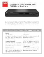
background image

(No.YD054)3-3

General assembly

Block No. [M][1][M][M]

Symbol No.

Part No.

Part Name

Description

Local

  1

GN10059-023A

FRONT PANEL

420UC,420US

  1

GN10059-024A

FRONT PANEL

422UC,422US

  2

GN40020-002A

JVC MARK

  3

GN20111-001A

WINDOW SCRREN

  4

GN20110-003A

PUSH BUTTON

420UC,420US

  4

GN20110-004A

PUSH BUTTON

422UC,422US

  5

QYSDSF2608ZA

TAP SCREW

FOR PUSH BUTTON(x3)

  6

GN10061-001A

CHASSIS BASE

  7

GN40054-002A

FELT SPACER

REAR FOOT(x2)

  8

QYSBSGG3006EA

TAP SCREW

VFD CB+CHASSIS(x2)

  9

QYSBSGG3006EA

TAP SCREW

M3 x 6mm(x4)

 10

GN30126-001A

BRACKET

(x2)

 11

QYSBSGG3006EA

TAP SCREW

DIGITAL CB+BRACKET(x2)

 12

QUQ210-0520CC

FFC WIRE

MECHA TO DIGITAL

 13

QUQ210-2306CJ

FFC WIRE

MAIN TO DIGITAL

 14

QUQ210-1303CJ

FFC WIRE

MAIN TO DIGITAL

 15

QUQ210-0703CJ

FFC WIRE

MAIN TO DIGITAL

 16

QUQ212-1724CJ

FFC WIRE

VFD TO MAIN 

 17

------------

TRAVERSE MECHANISM

 18

LE40900-003A

INSULATOR

(x2)

 19

LE40900-005A

INSULATOR

(x2)

 20

LE40901-002A

SPECIAL SCREW

FOR INSULATOR(x4)

 21

------------

LOADING MECHANISM

 22

GN30118-001A

FFC HOLDER

FOR FFC WIRE

 23

QYSDSF2608ZA

TAP SCREW

FFC HOLDER

 24

GN30006-028A

SPACER

(x2)

 25

QYSBSG3006ZA

TAP SCREW

MECHA+CHASSIS(x3)

 26

QQR1652-001

F.CORE

 27

LE30001-031A

SPACER

(x2)

 28

GN20115-003A

REAR PANEL

420UC,420US

 28

GN20115-004A

REAR PANEL

422UC,422US

 29

QYSBSGY3008MA

TAP SCREW

REAR+CHASSIS

 30

QYSBSGY3008MA

TAP SCREW

AUDIO OUT

 31

QYSBSGY3008MA

TAP SCREW

VIDEO OUT

 32

QYSBSGY3008MA

TAP SCREW

COAXIAL

 33

QYSBSGY3008MA

TAP SCREW

COMPU LINK

 34

QMF5AU1-1R6-J1 

FUSE

1.6A AC125V

 35

QMPD590-170-JN

POWER CORD(US/CA)

1.7m BLACK

 36

QZW0004-001

WIRE CLAMP

 37

GN20114-001A

TOP COVER

420UC,420US

 37

GN20114-002A

TOP COVER

422UC,422US

 38

QYSBSGG3006EA

TAP SCREW

REAR(x3)

 39

QYSDSG3008MA

TAP SCREW

SIDE(x2)

420UC,420US

 39

QYSDSG3008NA

TAP SCREW

SIDE(x2)

422UC,422US

 40

GN20112-001A

FITTING

420UC,420US

 40

GN20112-002A

FITTING

422UC,422US

 41

GN20116-001A

REAR COVER

 42

QYSBSGY3008MA

TAP SCREW

M3 x 8mm

 43

LE40906-001A

S.SCREW

 44

LE40899-001A

YOKE

 45

LV42930-003A

MAGNET

 46

LE31046-003A

CLAMPER

Summary of Contents for XV-N420B

Page 1: ...IONS 1 7 3 DISASSEMBLY 1 8 4 ADJUSTMENT 1 15 5 TROUBLESHOOTING 1 18 Area Suffix US U S A UC Canada XV N420BUSC XV N420BUCC XV N422SUSC XV N422SUCC V I D E O OPEN CLOSE LIST SET UP CLEAR SLOW DISPLAY ON SCREEN ENTER STANDBY ON VFP I P CANCEL RETURN SOUND EFFECT TITLE GROUP DIMMER AUDIO SUBTITLE ANGLE SLIDE EFFECT ZOOM 1 2 3 4 5 6 7 8 9 0 THUMBNAIL TOP MENU MENU NEXT PREVIOUS SELECT ...

Page 2: ...deo outputs COMPONENT pin jacks Y Output 1 0 Vp p 75 Ω Pb Pr Output 0 7Vp p 75 Ω VIDEO pin jack 1 0 Vp p 75 Ω S VIDEO S jack Y Output 1 0 Vp p 75 Ω C Output 286 mVp p 75 Ω Horizontal resolution 500 lines or more Audio outputs ANALOG OUT pin jack 2 0 Vrms 10 kΩ DIGITAL OUT COAXIAL 0 5 Vp p 75 Ω termination Audio characteristics Frequency response CD sampling frequency 44 1 kHz 2 Hz to 20 kHz DVD sa...

Page 3: ...arts of the product an tenna terminals knobs metal cabinet screw heads headphone jack control shafts etc to be sure the product is safe to operate without danger of electrical shock Do not use a line isolation transformer during this check Plug the AC line cord directly into the AC outlet Using a Leakage Current Tester measure the leakage current from each exposed metal parts of the cabinet partic...

Page 4: ...verse unit optical pickup 1 Do not subject the traverse unit optical pickup to strong shocks as it is a sensitive complex unit 2 Cut off the shorted part of the flexible cable using nippers etc after replacing the optical pickup For specific details refer to the replacement procedure in the text Remove the anti static pin when replacing the traverse unit Be careful not to take too long a time when...

Page 5: ... C712 C713 C730 B724 C901 C902 C903 C904 C905 C906 C907 C908 C909 C950 C954 C955 C956 C957 C958 C959 C964 C966 C982 C983 C985 CN901 CN902 CN903 B752 CN905 B916 D902 B915 D906 D951 D952 D953 D954 D955 D956 D957 D960 EP902 FC901 FC902 IC901 IC902 J601 J602 J703 J901 L701 L702 L706 L707 L709 L730 L901 L951 L952 L953 L954 L955 L960 P901 PC901 Q951 B731 B730 R901 R902 R950 S501 S502 S503 S504 S505 S506...

Page 6: ...setting of these half fixed resistors for laser power adjustment 1 9 2 Destruction of Traverse Unit and Laser Pickup by Static Electricity Laser diodes are easily destroyed by static electricity charged on clothingor the human body Before repairing peripheral elements of the traverse unit or pickup be sure to take the following electrostatic protection 1 Wear an antistatic wrist wrap 2 With a cond...

Page 7: ... No YD054 1 7 SECTION 2 SPECIFIC SERVICE INSTRUCTIONS This service manual does not describe SPECIFIC SERVICE INSTRUCTIONS ...

Page 8: ...and lower part of the rear of the top cover with opening them slightly in an outward direction And the top cover will be removed Fig 1 3 1 2 Removing the front panel assembly See Figure 2 Prior to performing the following procedure remove the top cover There is no need to remove the mechanism assembly 1 Hook a and b are removed respectively and the front panel assembly is removed Fig 2 B B B A x 2...

Page 9: ... CN202 CN101 on the digital board ATTENTION Please extract the wire after short circuited of two places on the pick up unit in part c with solder Please remove the solder two places of part c after connecting the wire with CN101 when reassembling CAUTION Be sure to solder the short land sections c on the pick up unit before disconnecting the card wire from connec tor CN101 on the digital board If ...

Page 10: ...ush a lever until it can not be inserted any further 2 A tray is made to slide ahead 3 Remove the two screws F attaching the shaft guide Fig 6 Fig 7 3 1 5 Removing the rear panel See Figure 8 Prior to performing the following procedure remove the top cover 1 Remove the five screws G attaching the rear panel 2 Disconnect the power cord from connector P901 on the main board Fig 8 Tray Push F Tray F ...

Page 11: ...n the digital board 3 Disconnect the card wire from connector CN903 on the main board 4 Remove the four screws I attaching the main board Fig 9 Fig 10 3 1 7 Remove the FL Display board See Figure 11 Prior to performing the following procedure remove the top cover 1 Disconnect the card wire from connector CN501 CN503 on the FL Display board 2 Remove the two screws J attaching the FL Dispiay board F...

Page 12: ...e elevator See Figure 2 and Figure 3 Prior to the following procedure remove the traverse mecha nism assembly 1 Remove the two arms of the elevator from the two parts a by moving the arms in a direction of the arrow 2 Pull out the elevator in a rear direction Attaching the elevator Engage the two holes b to the two shafts on the front part of the elevator And then attach the elevator Fig 2 Fig 3 L...

Page 13: ...ng procedure remove the tray the traverse mechanism assembly and the elevator 1 Remove the belt from the pulley 2 Remove two screws B attaching the loading motor 3 Remove two solders c on the switch board Fig 4 Fig 5 Loading base Slide cam Belt B B Pulley Pulley Loading motor Switch board Part c ...

Page 14: ...f spring 3 Lift d of the shaft 1 and pull out the shaft 1 from e 4 Remove f of the pickup from the shaft 2 Attaching the pickup 1 Engage f of the pickup to the shaft 2 2 A spring is lifted and shaft 1 is inserted in the e and at tach the shaft 1 to d 3 Attach the leaf spring and then attach the plate Fix the leaf spring and the plate by using the screw C Fig 6 Fig 7 C Plate Leaf spring spring Part...

Page 15: ... whether the symptoms are improved or not After servicing before returning the main body to a customer Initialized main body should be returned to a customer 1 Set the main body at test mode 2 Press FWD SKIP key of the main body 3 When indicate P on the FL display initialization is completed Becomes test mode Version of backend Type of flash memory Version of frontend Check mode N420 FL Display be...

Page 16: ...XXXX rom file in the root of CD R RW Folders such as jvc_dvd are not necessary 4 3 2 Upgrade method 1 Prepare upgrade disc with N420XXXX rom file written in its root 2 Press POWER key of the main body to turn the main body on 3 Insert the upgrade disc 4 The contents of disc are read automatically and upgrade is started 5 TV screen 1 28 2 28 if the count up is displayed and it becomes 28 28 it will...

Page 17: ...tion buttons should worked correctly with moderate click feeling Open and close movement of tray When press OPEN CLOSE button the tray should move smoothly without any noise Remote controller unit working Check the correctly operation in use of remote controller unit Reading of TOC Be not long in the malfunction Search Both forward searches and backward searches should be able to be done Do not st...

Page 18: ...nues for several seconds and becomes NO DISC or an error display afterwards The rotation of DISC becomes high speed and abnormal and becomes NO DISC or an error display afterwards Is focus retraction OK Even when it retracts correctly if it is out of focus and makes repeated retries with a clicking sound it is in error Is tracking retraction OK If TE waveform reappears or fails to converge after t...

Page 19: ...ocessor is defective IC101 APC circuit is defective Q101 Q102 Pattern is defective Lines for CN101 All patterns which relate to pick up and patterns between IC101 IC101 For signal from IC101 to IC301 is signal output from IC101 40 FE 5 2 3 Traverse movement NG 1 Defective traverse driver Has the voltage come between terminal of CN201 7 and 8 2 Defective BTL driver IC201 Has the motor drive voltage...

Page 20: ... 3 traverse movement NG in Check points for each error when it is not normal Are not there caught of the feeding mechanism etc 5 2 10 Picture is distorted or abnormal sound occurs at intervals of several seconds Is the feed operation normal Are not there caught of the feeding mechanism etc 5 2 11 Others The image is sometimes blocked and the image stops The image is blocked when going to outer tho...

Page 21: ... No YD054 1 21 ...

Page 22: ... No YD054 AV MULTIMEDIA COMPANY DIGITAL VIDEO STORAGE CATEGORY 12 3 chome Moriya cho kanagawa ku Yokohama kanagawa prefecture 221 8528 Japan Victor Company of Japan Limited VPT Printed in Japan ...

Page 23: ...SML200502 Area Suffix US U S A UC Canada XV N420BUSC XV N420BUCC XV N422SUSC XV N422SUCC V I D E O OPEN CLOSE LIST SET UP CLEAR SLOW DISPLAY ON SCREEN ENTER STANDBY ON VFP I P CANCEL RETURN SOUND EFFECT TITLE GROUP DIMMER AUDIO SUBTITLE ANGLE SLIDE EFFECT ZOOM 1 2 3 4 5 6 7 8 9 0 THUMBNAIL TOP MENU MENU NEXT PREVIOUS SELECT ...

Page 24: ... REC modes are the same PB mode REC mode 4 Voltage measurement 1 Regulator DC DC CONV circuits REC Colour bar signal PB Alignment tape Colour bar Unmeasurable or unnecessary to measure 2 Indication on schematic diagram Voltage indications for REC and PB mode on the sche matic diagram are as shown below 6 Indication of the parts for adjustments The parts for the adjustments are surrounded with the ...

Page 25: ...2 2 ...

Page 26: ...Pb Cr Pr COUT C Cv Y AVC 64M SDRAM IC302 Loading motor Tray switch S1 Tray illumination D1 D2 Flash ROM IC303 CN302 FROM Pick up Unit FROM Spindle motor assembly CN201 CN202 WOUT VOUT UOUT COM FM FM LM LM CLOSESW OPENSW TRVSW REMO FLDIN CLK STB STBY X301 LA0 to LA20 LWRL LOE LCS3 LD0 to LD7 VID_XO VID_XI AVC J901 Block diagram AC IN Line filter L901 AC DC D903 Switching regulator IC901 AC D D906 C...

Page 27: ...C501 Remote controller IC502 F F K1 K2 SG1 to SG4 VDISP STB FLDIN CLK GR1 to GR7 SG1 to SG9 REMO L707 IC704 AC DC D903 Power transformer T901 AC DC D906 C909 AC DC D952 C982 AC DC D955 C954 L952 AC DC D953 C983 L951 AC DC D954 C955 L953 AC DC D956 L954 C957 C985 AC DC D957 L955 C956 C966 ED BACK PC901 AC DC D951 C950 Q951 Operation switch S501 to S508 VDISP 12V 12V CN901 CN902 CN903 B5 7V M9V B3 3...

Page 28: ... 022 0 1 10K 0 1 NI NQR0022 005X 0 022 0 022 NI 0 B5 7V 470P DGND 560P M9V 560P B5 7V NI 0 1 120P 30K 22K 0 01 KRC107S X 10K 0 022 NI 0 1 MGND 100P 47K NI 680P 680P 0 1 RT1P141C X 47 6 3 DGND 100 0 1 NI B3 3V 0 1 0 1 0 0 1 16 D5V DGND 1 0 12P D3 3V QGF1044F1 13X NI 12P 0 1 1 NAX0770 001X 0 1 1 0 0 1 NI 1000P 1000P 2SK3019 X 2SK3019 X 33 33 33 33P 33P 33P 0 QGF0536C1 24W 3 3K 3 3K 0 1 1 0 1 NI 680P...

Page 29: ...2 001X 0 1 0 1 DGND 390 0 1 0 1 NI NI 1K NI 1K NI 1K NI 1K B3 3V DGND 4 7K 0 1 DGND 470p 0 1 NI NI NI NI NI NI 0 470p 33 470p 100 NI 0 470p 100 470p NI NQR0251 001X 100 33 MBM29LV160TE70 33 100 220 6 3 100 NI 100 100 33 100 100 100 33 100 33 NI NI NI 82 NI NI 100 0 1 NQR0502 001X NI 220 6 3 0 1 NI 3 3K 0 NI 82 470p 68 68 82 33 360 1K LCS3 LCS3 LA17 LA0 AOUTR AOUTL YOUT LCS2 REMO LCS2 LCS2 S1 RGB A...

Page 30: ... QQR1384 001 QGA7901C1 02 47 200 68K 22P 1000P NQR0129 002X 82 16 18K PS2581AL1 QW MIP2C40MP 220 0 1 390K 100 1 5k 1 1SS133 T2 TL432 A T 82 16 100 6 3 39 35 47 25 47 25 0 0022 0 QQR1633 001 0 3 9K QGF1208C1 17 0 022 50 22K 4700p 3 9K 0 1 MTZJ3 6B T2 0 DGND NI NI 1F4G T2 1F4G T2 1SS133 T2 10K 0 1 QLF0158 001 1SS133 T2 470 10 1F4G T2 QAL0552 001 0 1 100 6 3 0 1 100 6 3 100U 470 10 NI NI 330 16 1F4G ...

Page 31: ...P44QC X NI 1K QGF1201C3 17 NI QGF1040C1 13 QGF1040C1 07 NQR0251 001X QNS0221 001 100p 100 100 6 3 NI 100 200 0 1 3 9K 200 0 1 QNN0668 001 QNN0698 001 0 NI 3 9K 470P NI QSW0651 001Z 10K KRA104S X DGND 4 7K 10K 4 7K KRC102S X 2SC3928A Q X 2SA1530A Q X 620 QGF1208C1 17 2SC3576 JVC T 10k 10K RT1P441C X 4 7 1 5K 1 5k NQR0129 002X SN74AHCT08NS X 47K 22 25 RC4558D X RC4558D X 200 100 QSW0651 001Z 470P 0 ...

Page 32: ...A 1 2 3 4 5 B C D D3 D4 CN4 D1 D5 D6 D2 R1 NI UDZS7 5B X QGF1006F2 07W SELU1E10WXM P UDZS7 5B X NI SELU1E10WXM P 0 Mechanism switch and LED board section TO CN50 SHEET 2 2 9 ...

Page 33: ...D E F G CN1 S1 QGF1016F3 05 QSW1074 001 lvs30022001a_rev0 SHEET 3 TO CN503 SHEET 2 TO CN202 SHEET 1 2 10 ...

Page 34: ...743 C744 C745 C746 C748 C751 C752 C753 C771 C777 C790 C901 C903 C904 C952 C953 C989 FC901 FC902 IC701 IC704 J601 J602 J703 J901 K703 K901 L701 L702 L706 L707 L709 L730 L901 L960 P901 Q703 Q705 Q706 Q711 Q712 R70 R70 R706 R709 R711 R712 R714 R715 R716 R718 R723 R724 R725 R726 R727 R729 R732 R733 R735 R736 R737 R738 R739 R741 R752 R753 R754 R756 R757 R758 R771 R772 R773 R774 R775 R776 R779 R780 R781...

Page 35: ...952 Q960 Q961 Q962 Q963 R701 R703 R704 R705 R706 R709 R710 R713 R717 R728 R729 R734 R735 R736 R737 R752 R757 R758 R779 R790 R901 R902 R903 R904 R905 R906 R932 R934 R935 R950 R953 R954 R955 R956 R957 R958 R961 R962 R969 R981 R983 S501 S502 S503 S504 S505 S506 S507 S508 T901 L970 D903 C756 C755 R963 C917 C918 C919 C920 K504 K507 D905 C990 C991 K506 K505 K508 K509 K510 CP950 R778 R911 R912 CAUTION FO...

Page 36: ...01 C209 R215 R216 R217 C155 R314 R319 C310 R142 Q302 R322 C321 C102 C104 C105 C108 C113 C119 C125 C137 C138 C201 C204 C206 C211 C217 C251 C257 C258 C259 C263 C290 C304 C305 C306 C307 C308 C309 C317 C319 C320 C327 C331 C335 C337 C340 C344 C349 C350 C352 C355 C361 C362 C364 C365 C366 C367 C368 C369 C370 C371 C377 C380 C381 C385 C391 C392 C422 C423 CN404 D102 D103 D271 D301 IC201 IC302 IC303 K102 K10...

Page 37: ...56 C913 R313 R142 R145 C104 C105 C108 C113 C118 C119 C121 C124 C125 C137 C138 C144 C145 C149 C151 C180 C181 C182 C417 C418 C440 C965 C978 D102 D103 IC403 K102 K103 K333 Q101 Q102 Q103 Q130 R101 R103 R104 R105 R106 R107 R108 R109 R110 R111 R113 R114 R115 R116 R124 R125 R126 R127 R128 R131 R132 R133 R134 R135 R136 R174 R175 R351 R393 R394 R406 R412 R413 R414 R415 R417 R418 R419 R420 TP15 TP16 TP18 T...

Page 38: ...No YD054SCH Victor Company of Japan Limited AV MULTIMEDIA COMPANY DIGITAL VIDEO STORAGE CATEGORY 12 3 chome Moriya cho kanagawa ku Yokohama kanagawa prefecture 221 8528 Japan VPT Printed in Japan ...

Page 39: ...column shows the number of the used part XV N420B XV N422S Contents Exploded view of general assembly and parts list DVD Traverse mechanism assembly and parts list DVD Loading mechanism assembly and parts list Electrical parts list Packing materials and accessories parts list 3 2 3 4 3 6 3 8 3 12 Area Suffix US U S A UC Canada ...

Page 40: ... BACK SIDE Block No M1MM 39 38 38 37 39 38 A FRONT SIDE Operation switch board 5 4 1 2 3 6 7 7 8 b 8 9 11 9 9 10 13 14 c 15 16 17 18 18 19 19 20 20 20 20 21 40 25 24 25 a 35 36 34 26 42 30 32 31 33 27 27 41 29 43 44 45 46 A Digital board Main board VFD board 28 a c b 12 22 23 ...

Page 41: ...0 LE40901 002A SPECIAL SCREW FOR INSULATOR x4 21 LOADING MECHANISM 22 GN30118 001A FFC HOLDER FOR FFC WIRE 23 QYSDSF2608ZA TAP SCREW FFC HOLDER 24 GN30006 028A SPACER x2 25 QYSBSG3006ZA TAP SCREW MECHA CHASSIS x3 26 QQR1652 001 F CORE 27 LE30001 031A SPACER x2 28 GN20115 003A REAR PANEL 420UC 420US 28 GN20115 004A REAR PANEL 422UC 422US 29 QYSBSGY3008MA TAP SCREW REAR CHASSIS 30 QYSBSGY3008MA TAP ...

Page 42: ...rse mechanism assembly and parts list 16 12 13 14 15 Back side 25 20 Grease 1401C PG 641 CFD 4007ZY2 JVG 31N 17 6 21 22 23 8 9 7 10 19 18 2 1 3 4 11 Block No M2MM 27 63 3mm 0 1mm 10 5mm 0 1mm A A GXL Z1 21C 27 5 26 27 24 11 ...

Page 43: ... 10 QYSPSPU2040MA SCREW M2 x 4mm x2 11 QYSDST2604MA SCREW M2 6 x 4mm x3 12 QAL0577 001 PICK UP HOP 1400 13 LE20732 001A SW ACTUATOR 14 LE31093 001A LEAD SPRING 15 QYSPSFU1740ZA TAP SCREW M1 7 x 4mm x2 16 QUQ105 2420AC FFC 24pin 20cm 17 LE40931 001A SHAFT 18 LE40855 002A FEED GEAR E 19 LE40918 001A LEAD SCREW 20 LE40930 001A FEED GEAR M 21 LE40928 002A THURUST SPRING 22 LE40927 002A PLATE 23 QYSDST...

Page 44: ...g mechanism assembly and parts list Switch board Back side a b 8 a b Block No M3MM 5 3 19 21 2 4 1 18 17 FLM J4 11M FLM J4 11M 12 9 10 11 13 14 15 16 20 22 26 26 23 25 24 7 6 Back side NUT Grease 1401C SC306 FL 7750E JVG 31N ...

Page 45: ... C D ROLLER 10 E407149 001SS RUBBER TUBE 11 LV10933 003A TRAY 12 LV35050 001A SHAFT GUIDE 13 LV43847 001A SHAFT FOR TRAY 14 QYSSSP2010ZA SCREW FOR SHAFT 15 QYNNS2000ZA NUT M2 16 QYSDSF2008ZA TAP SCREW M2 x 8mm x2 17 QAR0197 001 MOTOR MABUCHI 18 LV43844 002A MOTOR PULLEY 19 QYSPSPU1730ZA SCREW FOR MOTOR x2 20 QYSDSF2008ZA TAP SCREW FOR C BOARD ASS 21 LV43974 001A BELT 22 LV21747 004A CLAMPER BASE 2...

Page 46: ...1CK 104X C CAPACITOR 0 1uF 16V K C744 NCB31HK 331X C CAPACITOR 330pF 50V K C745 NCB31HK 331X C CAPACITOR 330pF 50V K C746 NCB31HK 221X C CAPACITOR 220pF 50V K C748 NDC31HJ 470X C CAPACITOR 47pF 50V J C751 NCB31HK 151X C CAPACITOR 150pF 50V K C752 NDC31HJ 270X C CAPACITOR 27pF 50V J C753 NCB31HK 221X C CAPACITOR 220pF 50V K C771 NDC31HJ 470X C CAPACITOR 47pF 50V J C901 QFZ9073 823 MM CAPACITOR 0 08...

Page 47: ...TOR 0Ω 1 16W J K508 NRSA63J 0R0X MG RESISTOR 0Ω 1 16W J K509 NRSA63J 0R0X MG RESISTOR 0Ω 1 16W J K510 NRSA63J 0R0X MG RESISTOR 0Ω 1 16W J K511 NQR0251 001X FERRITE BEADS K512 NRSA63J 0R0X MG RESISTOR 0Ω 1 16W J K513 NRSA63J 0R0X MG RESISTOR 0Ω 1 16W J K514 NRSA63J 0R0X MG RESISTOR 0Ω 1 16W J K515 NRSA63J 0R0X MG RESISTOR 0Ω 1 16W J K516 NRSA63J 0R0X MG RESISTOR 0Ω 1 16W J K517 NRSA63J 0R0X MG RESI...

Page 48: ...C343 NCB31CK 104X C CAPACITOR 0 1uF 16V K C344 NEAF0GM 476X E CAPACITOR 47uF 4V M Symbol No Part No Part Name Description Local C349 NCF31CZ 104X C CAPACITOR 0 1uF 16V Z C350 NCF31CZ 104X C CAPACITOR 0 1uF 16V Z C351 NCF31CZ 104X C CAPACITOR 0 1uF 16V Z C352 NCF31CZ 104X C CAPACITOR 0 1uF 16V Z C353 NCB31HK 471X C CAPACITOR 470pF 50V K C357 NCF31AZ 105X C CAPACITOR 1uF 10V Z C358 NCF31CZ 104X C CA...

Page 49: ...100Ω 1 16W J R343 NRSA63J 101X MG RESISTOR 100Ω 1 16W J R344 NRSA63J 101X MG RESISTOR 100Ω 1 16W J R345 NRSA63J 101X MG RESISTOR 100Ω 1 16W J R346 NRSA63J 101X MG RESISTOR 100Ω 1 16W J R347 NRSA63J 101X MG RESISTOR 100Ω 1 16W J R348 NRSA63J 101X MG RESISTOR 100Ω 1 16W J R349 NRSA63J 101X MG RESISTOR 100Ω 1 16W J R350 NRSA63J 101X MG RESISTOR 100Ω 1 16W J R353 NRSA63J 0R0X MG RESISTOR 0Ω 1 16W J R3...

Page 50: ...3 12 No YD054 Packing materials and accessories parts list Block No M4MM P3 P1 P5 P4 P2 P6 A9 INST BOOK SA ACCESSORIES SA A4 A3 A2 A1 A10 A11 A8 A6 A5 A7 ...

Page 51: ...TY CARD BT 52006 1 420UC 422UC A 5 QAM0328 001 AV CORD 3P A 6 RM SXV069M REMOCON UNIT A 7 BATTERY R6TYPE x2 A 8 BT 51034 2 REGISTRATION CARD 420US 422US A 9 LE30964 001A NETFLIX COUPO 420US 422US A10 QPC02504015P POLY BAG 25cm x 40cm A11 QPC01503515 POLY BAG 15cm x 35cm P 1 QPC06005515P POLY BAG FOR SET P 2 GN10068 001A PACKING CASE 420UC 420US P 2 GN10068 002A PACKING CASE 422UC 422US P 3 GN20117...

Reviews: