XM-P55
XM-PJ1
2-23
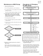
Maintenance of MD Pickup
1. Cleaning of pickup lens
(1) Prior to changing the pickup, clean the pickup lens.
(2) For cleaning the lens, use the following cotton swab after
mearsing it in alcohol.
Product No. JCB-B4; Manufacturer;Nippon Cotton Swab
2. Confirmation of the service life of laser
diode when the service life of the laser
diode has been exhausted, the following
symptoms will appear.
(1) Recording will become impossible.
(2) The RF output (EFM output and eye pattern amplitude)
will become lower.
(3) The drive current required for light emitting of laser diode
will be increased.
Confirm the service life according to the following flow chart:
Is the drive current
of laser diode
45mA or less?
Change the pickup
Change the pickup
NO
YES
OK.
NO
YES
4. Semi-solid state resistors on
the APC P.C. board
The semi-solid state resistor on the APC P.C.board
attached to the pickup is used for adjusting the laser
power. Since these resistor should be adjusted in
pair according to the characteristics of the optical
block, be sure not to touch on the resistors.
Since the service life of the laser diode will be
exhausted when the laser power is low, it is
necessary to change the pickup. Meanwhile, do not
pickup. Otherwise, the pickup will be damaged due
to over current.
3. Method of measuring the drive current of
laser diode
When the voltage measured at the both side of carbon resistor
R301 on the MD servo P.C. board (VMW2424A) have become
45mV or over, the service life of the laser diode is judged to have
been exhausted.
Procedures of Changing
the MD pickup
Change the MD pickup by referring
to "Removing the MD pickup" in the
Disassembly Method.
Set the pickup to [TEST] mode according
to the procedures described in the
Adjustment Method.
Adjust the laser power 75
.
Adjust the disc.
Completion of changing the MD pickup.
Since this system is designed to perform magnetic
recording, the laser power ten times or over of the
conventional MD player will be output. Therefore, be
sure to perform not only adjustment and operation
of this system so carefully as not to directly look at the
laser beam or touch on the body.
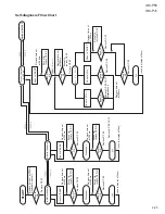
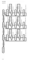
Can the laser power
adjust under test mode?
Is the power output
750
How to operation
Return to feed .
Return to feed .
Adjust the Pre D
have been become OK
Adjust the Mo D
have been become OK
Summary of Contents for XM-P55
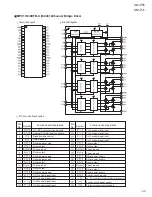
Page 7: ...XM P55 XM PJ1 2 5 CXD2655R IC351 Digital Servo Processor Block Diagram ...
Page 30: ...XM P55 XM PJ1 2 28 MEMO ...
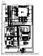
Page 34: ...A B C D 1 2 3 4 5 XM P55 XM PJ1 2 32 To BLOCK D To BLOCK A BLOCK C XM P55 Except to U S A ...
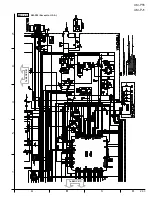
Page 35: ...A B C D 1 2 3 4 5 XM P55 XM PJ1 2 33 To BLOCK B BLOCK D XM P55 Except to U S A To BLOCK C ...
Page 36: ...XM P55 XM PJ1 2 34 MEMO ...
Page 37: ...A B C D E F G 2 35 XM P55 XM PJ1 2 9 2 9 2 9 Ý P55J ONLY ...
Page 40: ...A B C D 1 2 3 4 5 XM P55 XM PJ1 2 38 To BLOCK A To BLOCK D BLOCK C XM PJ1 Except to U S A ...
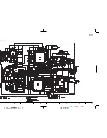
Page 41: ...A B C D 1 2 3 4 5 XM P55 XM PJ1 2 39 To BLOCK C To BLOCK B BLOCK D XM PJ1 Except to U S A ...
Page 42: ...XM P55 XM PJ1 2 40 MEMO ...
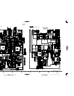
Page 43: ...A B C D E F G 2 41 XM P55 XM PJ1 2 9 2 9 2 9 Ý XM PJ1 J ONLY ...
Page 45: ...A B C D 1 2 3 4 5 XM P55 XM PJ1 2 43 Block No Block No Headphone Jack Board Switch Board ...
Page 46: ...XM P55 XM PJ1 2 44 MEMO ...
Page 49: ...XM P55 XM PJ1 3 3 ...
Page 50: ...A B C D 1 2 3 4 5 XM P55 XM PJ1 3 4 MD Mechanism Ass y and Parts List Block No MODEL PPM ...
Page 51: ...XM P55 XM PJ1 3 5 ...
Page 52: ...XM P55 XM PJ1 3 6 Electrical Parts List Main board ...
Page 53: ...XM P55 XM PJ1 3 7 ...
Page 54: ...XM P55 XM PJ1 3 8 ...
Page 55: ...XM P55 XM PJ1 3 9 Headphone Jack board Switch board ...
Page 57: ...XM P55 XM PJ1 3 11 Packing Parts list Accessories Parts list ...
Page 59: ...XM P55 XM PJ1 3 13 Packing Parts list Accessories Parts list ...
Page 61: ...XM P55 XM PJ1 3 15 Packing Parts list Accessories Parts list ...
Page 62: ...XM P55 XM PJ1 3 16 MEMO ...
Page 65: ...XM P55 XM PJ1 4 3 ...
Page 67: ...XM P55 XM PJ1 4 5 Electrical Parts List Main board ...
Page 68: ...XM P55 XM PJ1 4 6 ...
Page 69: ...XM P55 XM PJ1 4 7 ...
Page 70: ...XM P55 XM PJ1 4 8 ...
Page 71: ...XM P55 XM PJ1 4 9 Headphone Jack board Switch board ...
Page 73: ...XM P55 XM PJ1 4 11 Packing Parts list Accessories Parts list ...
Page 75: ...XM P55 XM PJ1 4 13 Packing Parts list Accessories Parts list ...
Page 77: ...XM P55 XM PJ1 Packing Parts List Accessories Parts List ...

