XM-P55
XM-PJ1
2-16
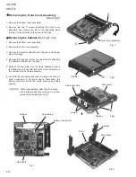
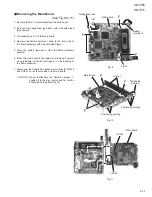
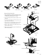
Removing the Front Cover Assembly
(See Fig.4)
Remove the bottom cover assembly.
Remove the two C screws attaching the front cover
assembly, and remove the front cover assembly while
turning it in the direction of the arrow in the Fig.4.
1.
2.
CAUTION: When reassembling, attach the harnesses
with a double-sided tape to the part c on the
inside of the cabinet (See Fig.8).
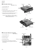
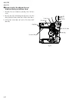
Removing the Cabinet (See Fig.5 to 8)
Remove the bottom cover assembly.
Remove the front cover assembly.
Remove the screw D attaching the cabinet on the upper
side of the body.
Reverse the body and remove the two E screws attaching
the cabinet on the back of the body.
Release the two joints b on the flame assembly side of
the battery case in the direction of the arrow, and remove
the cabinet from the flame assembly.
Unsolder the two harnesses (one is orange, the other is
gray) connected to the main board. Disconnect the
battery connector B with the brown harness by pulling
upward.
1.
2.
3.
4.
5.
6.
Fig. 8
Fig. 6
Fig. 5
Fig. 4
Fig. 7
Front cover assembly
C
C
D
Cabinet
E
Flame assembly
Main board
Joints b
Cabinet
Cabinet
Battery connector B
Unsoldering
Main board
Cabinet
Main board
Part c
Summary of Contents for XM-P55
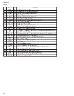
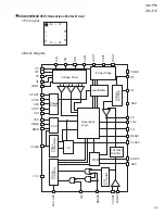
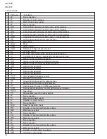
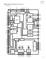
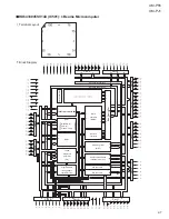
Page 7: ...XM P55 XM PJ1 2 5 CXD2655R IC351 Digital Servo Processor Block Diagram ...
Page 30: ...XM P55 XM PJ1 2 28 MEMO ...
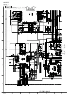
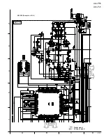
Page 34: ...A B C D 1 2 3 4 5 XM P55 XM PJ1 2 32 To BLOCK D To BLOCK A BLOCK C XM P55 Except to U S A ...
Page 35: ...A B C D 1 2 3 4 5 XM P55 XM PJ1 2 33 To BLOCK B BLOCK D XM P55 Except to U S A To BLOCK C ...
Page 36: ...XM P55 XM PJ1 2 34 MEMO ...
Page 37: ...A B C D E F G 2 35 XM P55 XM PJ1 2 9 2 9 2 9 Ý P55J ONLY ...
Page 40: ...A B C D 1 2 3 4 5 XM P55 XM PJ1 2 38 To BLOCK A To BLOCK D BLOCK C XM PJ1 Except to U S A ...
Page 41: ...A B C D 1 2 3 4 5 XM P55 XM PJ1 2 39 To BLOCK C To BLOCK B BLOCK D XM PJ1 Except to U S A ...
Page 42: ...XM P55 XM PJ1 2 40 MEMO ...
Page 43: ...A B C D E F G 2 41 XM P55 XM PJ1 2 9 2 9 2 9 Ý XM PJ1 J ONLY ...
Page 45: ...A B C D 1 2 3 4 5 XM P55 XM PJ1 2 43 Block No Block No Headphone Jack Board Switch Board ...
Page 46: ...XM P55 XM PJ1 2 44 MEMO ...
Page 49: ...XM P55 XM PJ1 3 3 ...
Page 50: ...A B C D 1 2 3 4 5 XM P55 XM PJ1 3 4 MD Mechanism Ass y and Parts List Block No MODEL PPM ...
Page 51: ...XM P55 XM PJ1 3 5 ...
Page 52: ...XM P55 XM PJ1 3 6 Electrical Parts List Main board ...
Page 53: ...XM P55 XM PJ1 3 7 ...
Page 54: ...XM P55 XM PJ1 3 8 ...
Page 55: ...XM P55 XM PJ1 3 9 Headphone Jack board Switch board ...
Page 57: ...XM P55 XM PJ1 3 11 Packing Parts list Accessories Parts list ...
Page 59: ...XM P55 XM PJ1 3 13 Packing Parts list Accessories Parts list ...
Page 61: ...XM P55 XM PJ1 3 15 Packing Parts list Accessories Parts list ...
Page 62: ...XM P55 XM PJ1 3 16 MEMO ...
Page 65: ...XM P55 XM PJ1 4 3 ...
Page 67: ...XM P55 XM PJ1 4 5 Electrical Parts List Main board ...
Page 68: ...XM P55 XM PJ1 4 6 ...
Page 69: ...XM P55 XM PJ1 4 7 ...
Page 70: ...XM P55 XM PJ1 4 8 ...
Page 71: ...XM P55 XM PJ1 4 9 Headphone Jack board Switch board ...
Page 73: ...XM P55 XM PJ1 4 11 Packing Parts list Accessories Parts list ...
Page 75: ...XM P55 XM PJ1 4 13 Packing Parts list Accessories Parts list ...
Page 77: ...XM P55 XM PJ1 Packing Parts List Accessories Parts List ...

