background image

13

The position memory function enables registration of the pan/tilt/zoom adjustment positions in the memory. Up to
10 positions (or 6 positions with the VN-C2U) can be registered in the memory.

1

Point the camera to the desired position by adjusting the [Camera Control] box.

2

Right-click on the desired one of the [Position Memory] buttons 1 to 10 (or 1 to 6 with the VN-C2U) and then
click on [Memory].

The position is now registered in the memory.

3

Henceforth, clicking on the [Position Memory] button points the camera to the position registered under the
button and the required image is displayed in the view window.

4

To change a previously registered position memory setting under a button, point the camera to a new position,
right-click on the same button and right-click on [Memory].

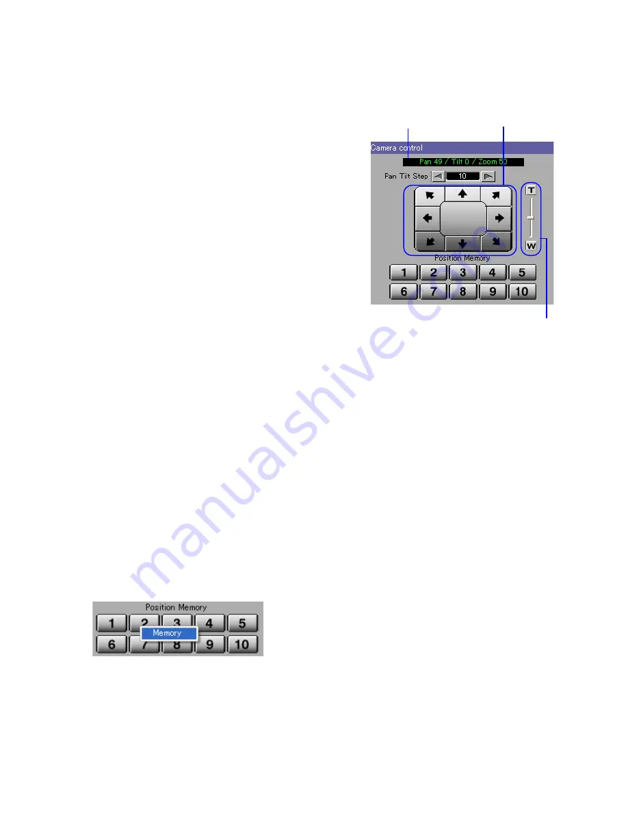
When a connected view point device is one of the models mentioned above, the [Camera Control] box is dis-
played below the live controller.

[Position Display]

Shows the current pan/tilt position and zoom setting.

[Pan Tilt Step]

Used to set the panning/tilting angle per click.

[Tele Single-Step Button]

Each click on the button zooms into the image.
(This function is disabled in case the View Point is VN-C2U.)

[Wide Single-Step Button]

Each click on the button zooms out of the image.
(This function is disabled in case the View Point is VN-C2U.)

[Pan/Tilt Adjustment Buttons]

Arrow buttons are provided to control the pan/tilt position
of the camera.
The panning/tilting angle per click can be set in the [Pan Tilt Step].

[Zoom Slider]

Dragging the mouse on this control adjusts the zoom ratio.
(This function is disabled in case the View Point is VN-C2U.)

[Position Memory]

Clicking on one of the buttons points the camera to the previously registered position. (See section 5-3, "Setting
the Position Memory" below for the method of setting the position memory positions.)

5-2. VN-C2U / C3U / C30U Controller

5-3. Setting the Position Memory

Position display

Pan/Tilt adjustment buttons

Zoom Slider and

Tele/wide single-step button

Summary of Contents for VN-S400U

Page 1: ...S400U User s Guide V1 1 Thank you for purchasing this JVC product This User s Guide has been compiled in order to describe the operating procedures for the product To enable a correct use of the product please read it carefully ...

Page 2: ... Note that this manual omits markings indicating registered trademarks trademarks and copyrights Before recording and storing image materials Copyright law prohibits the use without the permission of the copyright owners of the recording or storage of image reproductions such as TV broadcasts or prerecorded materials or of publications such as posters except for per sonal use Before recording impo...

Page 3: ...quential Interval 29 13 4 Setting the REC Indication 31 13 5 Setting the Connected View Point Information Display 29 13 6 Setting the Time Stamp Display 30 13 7 Setting the Alarm Message Display Colors 30 13 8 Setting the Recording File Save Location 31 13 9 Starting REC automatically by Opening the Work Space 32 13 10 Timelapse Recording 32 13 11 Alarm Recording 32 14 Play View Window Setup 33 14...

Page 4: ... following PC environment is required to effectively utilize the functions provided with the VN S400U PC machine Type PC AT compatible CPU Pentium III 1 GHz or higher Memory 256 MB or more Graphic board DirectX support 1024 x 768 or better True Color 24 bit or higher The on board video chip may sometimes malfunction Sound card Sound Blaster PCI recommended LAN card 100BASE TX Compatible OS Windows...

Page 5: ...Window and a View Window for displaying the images saved in the image files is referred to as a Play View Window The user can set the display size and position of each View Window View Point The devices connected to the network cameras and encoders are generically called the View Points Each View Point has a unique IP address View Channel The image output channel from each View Point is referred t...

Page 6: ...or the operation of the VN S400U Toolbar Shows the function icons The toolbar can be displayed or hidden by clicking on Toolbar in the Display menu View Window Area This area shows the View Windows Tree View Area Layout This area shows the icons of the registered View Windows and view points The Tree View Area Layout can be displayed or hidden by clicking on Tree View Area in the Display menu Cont...

Page 7: ...t View Window New View Window dialog box appears enter the name of the new View Window within 32 characters and click Register A Live View Window appears and the icon for the Live View Window is added in the Tree View Area Layout 4Register a View Point Open the Insert menu and select View Point The New View Point dialog box appears Enter the IP address and the name of the view point within 32 char...

Page 8: ...ee View Area Layout Click on of the recorded Live View Window icon to expand it and then click on of the info icon to expand it and click on the PC REC File icon The list of recorded image files will be displayed in the right half of the Tree View Area Layout The names of the image files are given automatically according to the date and time of the start of recording 9Play back the image of the se...

Page 9: ...ing the work space file The loca tion can be selected by clicking on Browse to open a folder browsing dialog box Set Template The template facility is convenient for creating a new work space by copying the View Window and view point setup of a previously saved work space When checking Set Template in this dialog box the previously saved work space may be specified for use as the template of the n...

Page 10: ...e time Check Multi Resister and enter the starting IP address and ending IP address in the IP Address boxes View Point Name The name of a View Point being handled on the VN S400U can be decided as required within 32 characters View Point Type Select Auto in usual use Select Unknown if the device of View Point is not in connectable condition In this case this View Point will be connected automatica...

Page 11: ...indow by repeating the above procedure It is not permitted to register a single view channel more than once in a Live View Window It is not permitted to register both of MPEG view channel and JPEG view channel in a Live View Window It is not permitted to register plural number of MPEG view channels in a Live View Window One MPEG view channel can be registered in a Live View Window Viewing the imag...

Page 12: ...ls Title Bar This shows the name of the active View Window A drop down list is provided to allow the selection of a different View Window name Stop Click on this button to stop the live image recording Rec Click on this button to start the live image recording To stop recording click on the Stop button Snap Shot Click on this button to save the image in the form of a still image See chapter 10 Sna...

Page 13: ... below the live controller Position Display Shows the current pan tilt position and zoom setting Pan Tilt Step Used to set the panning tilting angle per click Tele Single Step Button Each click on the button zooms into the image This function is disabled in case the View Point is VN C2U Wide Single Step Button Each click on the button zooms out of the image This function is disabled in case the Vi...

Page 14: ... with VN A1U can be controlled through this external device controller The type of the external device controller varies according to the connected device To use the external device controller it is needed to install the controller External Device Controller Package VN SE400U of each external device For the installation please access http www jvc victor co jp english pro vnetworks support index ht...

Page 15: ...ination folder name is Folder in which the work space is created Work space name View window name e g C Program Files JVC VN S400U Your Work Space View Window1 When recording is stopped a file with a name such as rec when the view channel is a JPEG view channel or asf when the view channel is a MPEG4 channel is created in the disk The file name section consists of 14 characters representing the y ...

Page 16: ...ist and click on the Timer Rec tab 4Click on the check boxes of the desired timer programs 1 to 7 This makes it possible to enter the timer recording time Enter the Start Time and End Time of the timer recording in the 24 hour system An End Time of 0 00 00 means the recording until the end of the day Note that it is not permitted to set a timer recording over a period of two days In Schedule selec...

Page 17: ...yout 2Click on the PC REC File icon below the name of the Live View Window used to record the image 3The list of the image files using the Live View Window is shown at the right hand side of the Tree View Area Layout If the recorded image file is ASF the mark is displayed with the Time information e g 2003 04 13 20 29 23 20 29 53 If there are image files more than 1000 the list is shown as follows...

Page 18: ...aving the desired image file 3Click on the Get File List button 4The list of the image files saved in the view point is shown at the right hand side of the Tree View Area Layout 5Double click on the file to be played back This starts playback of the file in the first Play View Window PlayView1 6If it is required to copy the local recording file in the PC select the file and click on the Copy Local...

Page 19: ...lider Shows the position being played back Drag the marker to seek a position in the image Fast Rewind Click on this button to play back the image in the backward direction Frame Backward Click on this button once to return the image by one frame Frame Advance Click on this button once to advance the image by one frame Fast Forward Click on this button to play back the image at high speed Stop Cli...

Page 20: ...ng the image section to be clipped 2While viewing the playback image click on the IN button at the desired point to specify it as the IN point 3While viewing the playback image click on the OUT button at the desired point to specify it as the OUT point 4To modify a previously specified IN or OUT point click on the IN or OUT button at the desired point The clipped image can be confirmed using the F...

Page 21: ...snap shots can be displayed simultaneously using the same proce dure 4In each Snap Shot window open the File menu and select Save As 5When the Save As dialog box appears specify the filename and the save location and then click on the Save button Please note when the Snap Shot is saved as a JPEG file The image is saved upside down if the Upside Down setting is effective in the View Point An oblong...

Page 22: ...en the Setting menu and select View Window to open the Live View Window Setting dialog box 3Click on Alarm tab 4Click on the button of the Target View Point box to open the drop down list and select the view point where the alarm operation is required If Disabled is checked the operation upon alarm reception will not be executed 5Under the Alarm 1 Alarm 2 Alarm 3 Motion Detect and Alarm 4 Relay Al...

Page 23: ... Change View Window is checked the View Window is displayed in the position and size set in this field Position Left Top The View Window is moved to the top left of the View Window area Not Move The View Window display position is not changed Size 160x120 The View Window size is changed to 160 x 120 320x240 The View Window size is changed to 320 x 240 640x480 The View Window size is changed to 640...

Page 24: ...ram file with as small a size as possible E mail Notice E mail messages are sent to the address specified in this field For modification of the address see section 12 5 Setting the E Mail Sending Address Upon Alarm Reception Specify the contents of the E mail Information Message The message set for Message is entered in the E mail text View Point Name IP Address The view point name and its IP addr...

Page 25: ...Alarm 2 To display a color frame around a View Window receiving an alarm it is required to select Highlight in section 11 2 Setting the Operation Upon Alarm Reception and specify enhancement of the View Window Alarm 3 Motion Detect Specify the color of the frame around the View Window receiving the Alarm 3 Motion Detect alarm 12 1 Setting the Tree View Area Layout Click on the Display Tag in the O...

Page 26: ...ion in a view point refer to the instruction manual of the relevant connected device of the view point Save Period Select the period for which the recording files are to be retained Non Limit File is retained for an unlimited period Days File is retained for the period specified in the box From 1 day to 200 days can be specified Disk Full Select the processing to be executed in case the disk runs ...

Page 27: ...date button 12 5 Setting the E Mail Sending Address Upon Alarm Reception Click on the Mail tab in the Option dialog box When E mail notice is selected as an operation upon alarm reception the E mail is sent to the address specified under this tab For the alarm see chapter 11 Alarm Setup SMTP Server name Specify the SMTP server name Port Number Specify the port number From Address Specify the mail ...

Page 28: ...select View Window It is also possible to setup by double clicking on the Live View Window icon on the Tree View Area Layout Click on the Display tab View Window Name The current View Window name is displayed If it is required to change the name enter the desired View Window name within 32 characters Window Size Select the size of the View Window Selecting Enable causes the motion grid color motio...

Page 29: ... enable sequential display click on the Sequential Start button in the live view controller Each click enables and disables the sequential display alternately When the sequential display is disabled the button becomes the Start Sequential button and the view channel list below the button is enabled The registered view channel can now be changed by clicking in this list 13 4 Setting the REC Indicat...

Page 30: ...arent is checked the background becomes transparent 13 5 Setting the Connected View Point Information Display This function displays the information on the view point being connected in the View Window Click on the desired Live View Window to make it active open its Setting menu and select View Window It is also possible to setup by double clicking on the Live View Window icon on the Tree View Are...

Page 31: ...Live View Window to make it active open its Setting menu and select View Window It is also possible to setup by double clicking on the Live View Window icon on the Tree View Area Layout Click on the Format tab Alarm Message Color and Alarm Message Back Color can be specified by clicking the respective Color Setting buttons If Transparent is checked the background becomes transparent For the conten...

Page 32: ...en the view channel is a JPEG view channel Click on the desired Live View Window to turn it active open its Setting menu and select View Window It is also possible to setup by double clicking on the Live View Window icon on the Tree View Area Layout Click on the Rec tab Recording interval can be specified between 1 and 120 seconds 13 11 Alarm Recording This function sets the conditions for recordi...

Page 33: ...sible to setup by clicking on the Play View Window icon on the Tree View Area Layout Click on the Display tab Selecting Enable causes the motion grid color motion area color and motion detect color to be displayed in the View Window Their display colors can also be specified for the procedures see section 12 2 Setting the View Window Highlight Frame Colors 14 3 Playback Mode Indication Click on th...

Page 34: ... to display the name of the View Point if the recorded file is ASF An ASF file asf is created when the view channel is a MPEG4 channel 14 5 Setting the Time Stamp Display Click on the desired Play View Window to make it active open its Setting menu and select View Window It is also possible to setup by clicking on the Play View Window icon on the Tree View Area Layout Click on the Format tab Time ...

Page 35: ...or the connected device The following setting is not available while recording is in progress 1In the Tree View Area Layout select the desired view point or the view channel 15 View Point Setup 2Open the Setting menu and select View Point The View Point Setting dialog box appears 3Enter the desired password within 8 characters in Password Enter the same password again in Re Type In setting of the ...

Page 36: ...ge clearer and less uneven Note that this option sets the size of the transferred image and does not set the size of the displayed View Window Fine Mode If checked the Fine Mode is effective It is effective only with the VN C10U Ver 1 4 or higher It is effective only by 640 x 480 image size Fine Mode makes the still image clear and detailed but the Fine Mode does not suite for the subject if it is...

Page 37: ...oint 1In the Tree View Area Layout select the desired view point or view channel 2Open the Setting menu and select View Point The View Point Setting dialog box appears Click on the External tab 3Check the connection terminal to be set COM1 or COM2 4Select the connected device model from Equipment Type 5Enter the connected device name within 32 characters This name is displayed in the View Channel ...

Page 38: ...indow menu and clicking Primary Window When the Primary Window is set a checkmark is displayed in the menu display Primary Window can be canceled by opening the Window menu and clicking Primary Window again When Primary Window is Set The VN S400U reduces the frame rates of the non active View Windows so that the frame rate of the image in the active View Window can be maintained at the set rate Wh...

Page 39: ...isplay sizes and positions of the View Windows Up to 4 load patterns can be registered 1Adjust the positions and display sizes of the View Windows 2Open the Window menu select Save Pattern and click on the desired one of the pattern numbers from No 1 through No 4 3To modify a previously registered load pattern set the View Window positions and sizes as desired perform step 2 above and click on the...

Page 40: ...lowing information 1 Registered View Points 2 View Channels JPEG channels MPEG4 channels 3 Information on each View Point External device connected to the View Point LOCAL REC Files Information on the files recorded in the connected device at the View Point 1Click on the View Channel to be viewed in the right half section 2Drag drop the selected View Channel on the Live View Window icon in the lef...

Page 41: ...d in the view point group 18 3 Playing Back a PC Recording File The PC recording files to be played back can be selected in the Tree View Area Layout For the operating procedure see section 8 1 Playing Back a PC Recorded File 18 4 Playing Back a Local Recorded File The local recording files to be played back can be selected in the Tree View Area Layout For the operating procedure see section 8 2 P...

Page 42: ...Select a View Point icon on the Tree View Area Layout and press Delete key or right click on the icon and select Delete from the displayed menu When the deletion confirmation message appears click on the OK button Note that the view points registered in the Live View Windows cannot be deleted Deleting a View Point Group Select a View Point Group icon on the Tree View Area Layout and press Delete k...

Page 43: ...ow name Within 32 characters Displays or hides the View Window Opens Live View Window Setting dialog box Deletes the View Window Changes the View Window name Within 32 characters Displays or hides the View Window Opens Play View Window Setting dialog box Deletes the View Channel Opens View Point Setting dialog box Opens View Point Control dialog box Tight click menu in the Play View window The set...

Page 44: ...Point name Within 32 characters Opens View Point Setting dialog box Opens View Point Control dialog box Changes the View Channel name Within 32 characters If the view channel name is modified during recording the view channel will be recognized as another view channle in its playback Opens View Point Setting dialog box Opens View Point Control dialog box Changes the extra device name Within 32 cha...

Page 45: ...the registrations that have been made including those of the Live View Windows and view points To exit a work space open the File menu and select Close Work Space 20 2 Opening a Saved Work Space To open a previously saved work space open the File menu and select Open Work Space When the Open dialog box appears select the work space file vxw from its save location and click on the Open button ...

Page 46: ...PU usage about 80 or lower by reducing the number of View Windows setting the frame rate lower or displaying the image in small size During the operation of VN S400U keep your PC not to become System standby or Turn off hard disks VN S400 will malfunction if the PC turns to System standby or Turn off hard disks The settings of System standby and Turn off hard disks are in the Control Panel Power O...

Page 47: ...COMPANY OF JAPAN LIMITED is a registered trademark owned by VICTOR COMPANY OF JAPAN LIMITED is a registered trademark in Japan the U S A the U K and many other countries 2003 VICTOR COMPANY OF JAPAN LIMITED c ...

Reviews: