background image

4

English

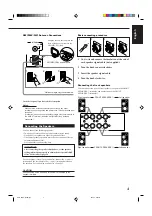
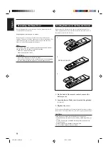
Basic connecting procedure

1 Cut, twist and remove the insulation at the end of

each speaker signal cable (not supplied).

2 Turn the knob counterclockwise.

3 Insert the speaker signal cable.

4 Turn the knob clockwise.

Connecting the front speakers

You can connect two pairs of front speakers (one pair to the FRONT
SPEAKERS 

1

 terminals, and another pair to the FRONT

SPEAKERS 

2

 terminals).

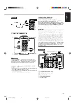
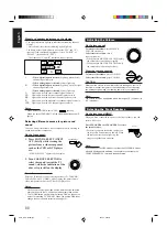
AM (MW/LW) Loop Antenna

Snap the tabs on the loop into the
slots of the base to assemble the
AM (MW/LW) loop.

Outdoor single vinyl-covered wire

Turn the loop until you have the best reception.

Notes:

• Make sure the antenna conductors do not touch any other

terminals, connecting cords and power cord. This could cause poor
reception.

• If reception is poor, connect an outdoor single vinyl-covered wire to

the AM EXT terminal. (Keep the AM (MW/LW) loop antenna
connected.)

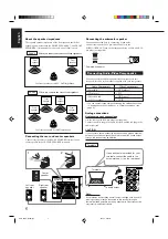
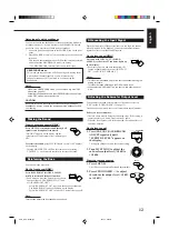
Connecting the Speakers

You can connect the following speakers:
• Two pairs of front speakers to produce normal stereo sound.
• One pair of rear speakers to enjoy the surround effect.
• One center speaker to produce more effective surround effect (to

emphasize human voices).

• One subwoofer to enhance the bass.

IMPORTANT:

After connecting the speakers listed above, set the speaker
setting information properly to obtain the best possible DSP
effect. For details, see page 14.

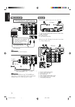
For each speaker (except for a subwoofer), connect the (–) and (+)
terminals on the rear panel to the (–) and (+) terminals marked on
the speakers. For connecting a subwoofer, see page 5.

ANTENNA

AM

EXT

AM

LOOP

FM  75  
COAXIAL

2

3

1

RIG

HT

1

2

1

RIG

HT

1

3

RIG

HT

1

4

FRONT SPEAKERS 

1

Left speaker

Right speaker

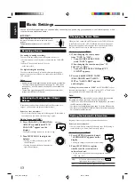
CAUTION:

Use speakers with the SPEAKER IMPEDANCE indicated by the
speaker terminals.

FRONT SPEAKERS 

2

Left speaker

Right speaker

AM (MW/LW) Antenna Connections

+

+

RIGHT

LEFT

1

2

1

2

FRONT SPEAKERS

EN01_09.RX-7000R[E]/f

00.4.24, 2:59 PM

4

Summary of Contents for RX-7000RBK

Page 1: ...REAR L CD DISC MODE ON OFF EFFECT REAR R SOUND SEA MODE SUBWOOFER RETURN SET MENU AUDIO TV VCR EXIT TEXT DISPLAY SLEEP 1 2 3 4 5 6 7 P 8 9 10 0 10 100 FM MODE CATV DBS MENU MENU ENTER ENTER TV CATV DBS VCR PTY SEARCH PTY PTY RX 7000R AUDIO VIDEO CONTROL RECEIVER STANDBY SPEAKERS 1 2 PHONES SURROUND ON OFF DSP MODE BALANCE SURROUND ADJUST SEA MODE SEA ADJUST SETTING MULTI JOG MASTER VOLUME SOURCE S...

Page 2: ...heck Electrical shock hazard testing After re assembling the product always perform an isolation check on the exposed metal parts of the product antenna terminals knobs metal cabinet screw heads headphone jack control shafts etc to be sure the product is safe to operate without danger of electrical shock Do not use a line isolation transformer during this check Plug the AC line cord directly into ...

Page 3: ... body 1 2 3 Removing the rear panel See Fig 4 Prior to performing the following procedure remove the top cover Disconnect the card wire from connector CN400 on the main board and CN402 on the power supply board in the front panel assembly Cut off the tie band fixing the harness Disconnect the harness from connector CN202 on the video board Remove the three screws C attaching the front panel assemb...

Page 4: ...ard Disconnect the DSP board from connector CN501 and CN601 on the main board while removing the DSP board from the bracket fixing the lower part of the DSP board at the same time Disconnect the compulink board from connector CN255 on the main board 1 2 3 4 5 6 7 8 Removing each board connected to the rear side of the main board See Fig 5 to 9 Fig 5 Fig 6 Fig 7 Fig 8 Fig 8 Fig 9 CN202 Main board C...

Page 5: ...CN712 CN931 and CN932 CN961 Remove the screw G attaching the regulator board to the heat sink cover Remove the eight screws H attaching the main board to the heat sink cover Remove the five screws I and the screw J attaching the main board to the chassis base The resistor board will come off at the same time 1 2 3 4 5 6 7 8 Prior to performing the following procedure remove the top cover Disconnec...

Page 6: ... harnesses connected to the power fuse board 1 2 Removing the power fuse board See Fig 16 Prior to performing the following procedures remove the top cover Unsolder the two harnesses connected to the power transformer Disconnect the harness from connector CN811 and the harnesses connected to connector CN55 and CN56 on the power transformer board Remove the four screws M attaching the power transfo...

Page 7: ...ee Fig 17 and 18 Prior to performing the following procedure remove the top cover and the front panel assembly Pull out the volume knob on the front side of the front panel and remove the nut attaching the system control board Remove the six screws P attaching the system control board on the back of the front panel and disconnect the harness from connector CN422 on the system control board Disconn...

Page 8: ...l On the back of the front panel release the four joints by pushing the joint tabs inward Remove the operation switch board toward the front Pull out the multi jog knob and the source selector knob Remove the two screws S attaching the operation switch board 1 2 3 4 Removing the operation switch board See Fig 21 to 23 Fig 21 Fig 22 Fig 23 Front panel R R R Joint Multi jog knob Source selector knob...

Page 9: ...88 for R ch so that the DC voltmeter value has 1mV 10mV Power amplifier section TP781 4 3 2 1 Lch Rch VR787 Lch VR788 Rch Heat sink Main board Adjustment of idling current Measurement location TP781 Adjustment part VR787 Lch VR788 Rch Attention This adjustment does not obtain a correct adjustment value immediately after the amplifier is used state that an internal temperature has risen Please adju...

Page 10: ...DVDD DVSS PD XTS ICKS1 ICKS0 CAD1 CAD0 CDTO CDTI CCLK CS PIS XTO XTI AVSS AVDD VREFH VCOM 1 Pin layout LIN LIN RIN RIN LOUT1 ROUT1 LOUT2 ROUT2 LOUT3 ROUT3 LPF LPF LPF LPF LPF LPF DAC DAC DAC DAC DAC DAC DATT DATT DATT DATT DATT DATT ADC ADC HPF HPF Audio I F MCLK BICK LRCK SDOUT SDIN1 SDIN2 SDIN3 SDTO SDTI1 SDTI2 SDTI3 SDOS DAUX Format Converter Block Diagram DIR and AC 3 DSP are external parts 2 ...

Page 11: ...ntrol register if P S L De emphasis pin ORed with serial control register if P S L De emphasis Pin ORed with serial control register if P S L Master clock output pin Digital power supply pin Digital ground pin Power down Reset pin When L the AK4527 is powered down and the control registers are reset to default state If the state of CAD0 1 changes then the AK4527 must be reset by PDN X tal oscillat...

Page 12: ... clock pin in serial mode Loop back mode pin in parallel mode Enables digital loop back from ADC to 3 DACs Control data input pin in serial mode Loop back mode pin in parallel mode Enable all 3 DAC channels to be input from SDTII Control data output pin in serial mode Pin Name VREFL VCOM VREFH AVDD AVSS XTI XTO MCKI P S DIF0 CS DIF1 CCLK LOOP0 CDTI LOOP1 CDTO Function I O I O I I O I I I I I I I I...

Page 13: ...PEN DRAIN 12BIT STRAGE RESISTER 12BIT SHIFT RESISTER 1 Terminal Layout 1 2 3 4 5 16 17 18 Vss DATA CLOCK LCK Q0 Q11 OE Vdd I I I O I Connect to GND Serial Data input Shift Clock of Data Latch Clock of Data Parallel Data Output Output Enable Power Supply Pin No Symbol I O Function Latch Data L H OUTPUT ON OFF 2 Pin Function BU2092 IC402 IC405 LED Controller ...

Page 14: ...ER AM OSC REG AM RF AFC AM AGC O I O I I I AM Local oscillation Signal output This is a terminal of AM Local oscillation circuit Register value between pin 26 and pin28 besides the frequency width of the input signal AM RF signal input This is an output terminal of voltage for FM AFC This is an AGC voltage input terminal for AM O O I O AM detection output FM detection output Mpx input terminal O O...

Page 15: ... output port Input output port Data input output Function IF counter signal input IF signal output Not use AM Local OSC signal output FM Local OSC signal input Power suplly VDD 4 5 5 5V When power ON Reset circuit move PLL charge pump output H Local OSC frequency Height than Reference frequency L Low Agreement Height impedance Input for active lowpassfilter of PLL Output for active lowpassfilter o...

Page 16: ...minal from CPU Shumit inverter style 4 10 19 25 f1 f7 Joint terminal of B P F f1 f7 X Right Left Total 14 terminal 11 12 TEST1 TEST2 Internal test terminal of IC It can use open condition IN 1 IN 2 Select terminal for 2 tip use 1 input key code 7C3 VDD joint 0 input key code 7C2 VEE joint 13 S 2 IN1 3 IN2 27 IN1 26 IN2 19 20 21 22 23 24 25 f1 f2 f3 f4 f5 f6 f7 10 f1 9 f2 8 f3 7 f4 6 f5 5 f6 4 f7 1...

Page 17: ...terminal DSP control signal terminal No use Reset signal input terminal Tuner chip enable Tuner clock signal terminal No use Tuner control signal terminal Tuner mute signal terminal Tuner signal input terminal Stereo signal input terminal Data start signal for block data to output serial data Busy signal from IC400 Inhibit signal input OSD data signal input terminal OSD standby signal terminal OSD...

Page 18: ...C EXHSYN EXVSYN Vss Dot CLK OSC CGROM Output Control Video Signal OSC Analog SW 4FSC CLK OSC VRAM Display Memory Control NTSC PAL Signal OSC H V Separate Serial Input Control SCLK SIN COUT YOUT VOUT VOB VOC IOUT GOUT ROUT BOUT EXD XD EXS XS CIN YIN VIN CS VSYNC HSYNC EXVSYN EXHSYN Each Block Each Control Data Each Block 1 Terminal layout 2 Block diagram MB90088PF 131 IC203 On screen display contro...

Page 19: ...uit terminal for color burst Horizontal signal output terminal Vertical signal output terminal EXT horizontal signal input terminal EXT vertical signal input terminal GND Dot clock generater outside circuit signal terminal for indication Character background signal output terminal Color signal Green Red Blue Test signal input terminal Shift clock input terminal for serial transmission Serial data ...

Page 20: ... IC400 FL Display Operation switch control 1 Pin layout 2 Key matrix 3 Pin function Symbol Description FL Segment control signal Power supply terminal FL grid control signal Key matrix output Source select JOG1 2 Volume JOG 3 4 BUSY Signal output to IC401 Clock signal to IC401 Command data input from IC401 Status signal output to IC401 Chip select signal input from IC401 Remote control signal inpu...

Page 21: ...I 1 Function 2 Terminal Lay out Block Diagram A0 A16 I O1 I O8 CS WE OE Vdd Vss Address inputs Data inputs outputs Chip select inputs Write enable input Output enable input Power supply Ground Symbol Description A0 A1 A2 A3 CS I O1 I O2 VDD VSS I O3 I O4 WE A4 A5 A6 A7 A16 A15 A14 A13 OE I O8 I O7 VSS VDD I O6 I O5 A12 A11 A10 A9 A8 1 2 3 4 5 6 7 8 9 10 11 12 13 14 15 16 32 31 30 29 28 27 26 25 24...

Page 22: ...al B Audio interface data input terminal 0 Audio interface data input terminal 1 Power supply for digital circuit Audio interface LR clock output terminal A Audio interface bit clock output terminal A Test input terminal 0 1 L test H operation usually Non connect Test input terminal L test H operation usually SPDIF input terminal Ground terminal for digital circuit Test sub input terminal 0 L test...

Page 23: ... Pin function Pin No 1 2 3 4 5 6 7 8 9 10 11 12 Symbol VSS L OUT NC NC L LD1 L LD2 L A GND NC CS1 NC NC CK Function Negative power supply pin Volume output pin No connection No connection Loudness tap output pin Loudness tap output pin Analog GND pin No connection Chip select input pin No connection No connection Data transfer clock input Pin No 13 14 15 16 17 18 19 20 21 22 23 24 Symbol DATA STB ...

Page 24: ...nal Connect to GND Connect to GND Connect to GND Non connect Power supply terminal Not use Non connect Communication port from IC401 Status communication port to IC401 Clock input from IC401 Ready signal input from IC401 Non connect Interface I O terminal with microcomputer Interface I O terminal with microcomputer of clock signal Interface I O terminal with microcomputer of chip select Interface ...

Page 25: ...2 8 11 2 9 10 7 MPX AFIN LVIN VDDA VSSA Vref TCON MRO OSCI OSCO VSSD MAD SCL SDA MPTH PSWN DAVN VDDD CIN SCOUT MRO NC GND OSCO OSCI VSSD VDDD DAVN SDA SCL NC GND NC VDDA VSSA MPX Vref SCOUT CIN NC 1 2 3 4 5 6 7 8 9 10 11 12 13 14 15 16 17 18 19 20 Function I O Symbol Pin No Multi path rectifier output Non connect Test control input pin Oscillator output Oscillator input Digital ground 0V Digital p...

Page 26: ...1 26 RX 7000RBK MEMO ...

Page 27: ...IN DVD IN MOUT C MOUT Y CMON1 YMON1 CN450 CN205 CN243 CN432 CN420 CN422 CN430 TO POWER AMP SECTION CN400 MONITOR DVD TV BS VCR1 OUT IN4 IN5 IN1 J241 J242 J243 DISPLAY MODE TA NEWS INFO EON PTY SEARCH SW S403 S406 KI0 KI4 KO4 SEA CONTROLLER IC451 SOUCE SELECTOR IC321 SEADATA SEACLK TUCE TUCK TUDATA TU L R DSPOUT SL SR A SWCLK A SWDATA A SWSTB DSPCLK DSPSTATUS DSPCOMMAND DSPREADY DSPRESET FRONT L R ...

Page 28: ...576MHz CLOCK X671 6 14MHz IC621 IC622 IC631 DSP IC641 SDRAM IN L R IC501 IC511 LOUT1 ROUT1 LOUT3 ROUT3 IC521 IC531 IC551 IC581 IC591 IC561 IC571 OUT L R OUT C OUT LFE OUT SL SR LOUT2 ROUT2 X1 X2 CDTI CDTO CCLK CS SDTI0 3 LRCLK BCLK SELECT1 4 DSPRESET DSPREADY DSPCOMMAND DSPSTATUS DSPCLK AUTODATA LOCK DIGITALO FORMAT CHANNEL ERR RST_DET WE OE CE I O8 1 A0 16 RX XI XO OPTICAL IN 1 2 UN661 UN662 DIGI...

Page 29: ...1 D54 D52 C55 D56 R54 C1 T2 R67 2SC2240 GL MTZ6 2JC KRC102M 22K 2SB1357 EF MTZ33JC 22 50 470 1SR139 1SR139 1SR139 220 50 QAD0095 4R7 100K 0 1MY 0 1MY KRC107M 1 3300 35 2200 35 0 1MY 1SR35 400A 10E2 FD 10E2 FD 1SS133 5 6K 8 2K 10K 4 7 50 2SC2235 O Y KRC105M 1SR35 400A 1000 25 1SS133 470 16 QSK0098 001 0 0047 100 0 22 2 2 330P 330P 470 18 0 22 1 50 KRA104M 22 50 220 63 3 3k 0 047MY 0 047MY 1SR35 400...

Page 30: ...60 100p 560 68 750 100K 0 022 0 022 47 25 47 25 10K 10K NJM4580L 2 2 10K 10K 1 50 NJM4580L 1 2 10K 10K 1 50 BA15218N 2 2 15K 5 1K 1 50 BA15218N 1 2 10K 10K 1 50 BA15218N 2 2 10K 10K 1 50 BA15218N 1 2 10K 10K 1 50 68 68 68 68 68 10 50 2 2K 470 6 3 2 2K 2 7K 2 7K 220p 4 7 50 100K 100K 68 68 68 68 100K 100K 220p 68 100K 100K 220p 1K 470K KRA104M 1K 10K 2SC2878 AB 2SC2878 AB 2SA933S R S 2SC2878 AB 10K...

Page 31: ...2 2K 3 3K 1SS133 0 22 7W 100 25 0 0047 12 4 7 12 12 2SD637 Q R 390 470 500 1K 10 68P 68P 2SA933AS RS 47 100 100 16 620 18K 82K 10P 2SC2240 BL AB 2SC2240 BL AB 2K 2K 1SS133 100P 100P 100K 9 1K 2 2K 10 50 12 12 10 1K 1K 10 10 4 7 10 33 33 1SS133 1SS133 47P 390 390 200 200 10 47P 2SA1038S S 2SC2389S SE 2SB649A B C 0 22 7W 2 7K 4 7 KTC3199 GL 100K 12K 2SD637 Q R 1K 10 2SA933AS RS 10 22K 100 16 620 18K...

Page 32: ...73 Q1853 RY981 RY982 D981 R982 R981 R985 R987 Q1804 Q1832 TH832 R1832 R1834 Q1872 Q1874 R988 Q808 Q810 Q807 Q809 Q811 R942 R944 C813 C814 R945 R946 D809 C815 R991 R992 R993 100K 2SC2240 BL AB 1SS133 120K 12K 2 2K 10 50 47 25 2K 100K 5P 47 16 2SA1038S S 33P 0 01MY 10 2 2 50 3 3K 3 3K 3 3K 3 3K 1SS133 1SS133 200 200 2SD2390LD OPY 10 390 390 33 47P 47P 2SD2390LD OPY 2 7K 15K 1SS133 0 022 2SC2389S S E...

Page 33: ...330P 330P 330P 330P 330P 330P 330P 330P 0 022 470 470 470 470 470 470 330 330 220 100K 22 25 68 68 220 470 470 BA15218N BA15218N 10K 10K MTZ6 2JC MTZ6 2JC MTZ6 2JC 470 220 100 220 220 22 25 22 25 22 25 0 022 0 022 22 25 560P NJM4580L NJM4580L NJM4580L NJM4580L 4 7 50 4 7 50 4 7 50 4 7 50 4 7 50 4 7 50 NJM4580D NJM4580D 4 7 50 4 7 50 22 25 22 25 330P 330P 330P 330P 330P 330P 330P 330P 470P 390P 390...

Page 34: ...49 R222 R223 R224 R214 Q206 Q205 Q204 R219 R220 R221 C217 C218 X200 C221 C222 C223 C224 C225 47P 100P 100P 75 75 47K 47K 47P 47P 3 3 BA7626 BA7625 0 047 0 047 75 75 75 75 75 75 75 75 4 7 50 4 7 50 470 6 3 4 7 50 470 6 3 0 047 0 047 0 047 10K 10K KTA1267 YG 470 470 KTA1267 YG 0 047 BA7625 NJM2285D MB90088PF 131 75 47 10 0 01 KTA1267 YG 75 47K 75 330 330 75 330 75 4 7 50 4 7 50 470 6 3 4 7 50 470 6 ...

Page 35: ...104M KRC107M 1SS133 1SS133 100K 10K 10K 10K 470 330P 10K 1SS133 1SS133 4 7K 100K 330 100K 1SR35 400A 470K 470K 470K 1SS133 PHONO_LED LED_LCK1 CD_LED VCR1_LED TV_LED DVD_LED AM_LED FM_LED TAPE_LED 4 8_OUT VL VH SEA_DATA SEA_CLK VIDEO3 VIDEO4 S MUTE RDS_ST RDS_DATA RDS_DATA RDS_CLK DSP_READY DSP_RESET SW_DATA OSD_STB OSD_DATA OSD_CLK VIDEO1 VIDEO2 VIDEO3 VIDEO4 DVD_S C TV_S C VCR1_S C RDS_CLK TUNER_...

Page 36: ... BA15218F 47 47 0 1 DTC114YE 47K 47K 6 14MHz 0 1 47 6 3 BA15218F 0 1 0 47 5600p 4 7 25 4 7 25 18K 3900P 3900P 1K 1K 100K 100K 2 2 50 2 2 50 BA15218F BA15218F 0 1 0 1 2700P 2700P 1K 1K 1K 1K 0 01 0 01 3900P 3900P 1K 1K 100K 100K 2 2 50 2 2 50 BA15218F BA15218F 0 1 0 1 2700P 2700P 1K 1K 1K 1K 0 01 0 01 BA15218F BA15218F 10k 22P 0 1 0 1 22P 10k 3K 3K 100K 100K 1 0 50 1 0 50 3900P 1K 1K 100K 100K 2 2 ...

Page 37: ...21 C193 IC102 C135 C136 R142 C163 C141 C150 C185 C164 R144 R112 C149 C148 R143 C147 C186 C144 C199 R124 C123 C197 C101 R111 R140 QAU0119 001 DTA114Y 330 QAX0519 001Z 220 QAX0285 001Z 100 KTC3199 GL 1 50 1K 2SC535 BC 0 047 0 022 2 2K 68 1 4W F RES 100 10 12P 12P 4 7K SAA6588 QGB2501K2 12 12P QAX0402 001 10K 3 3K 5 6K 4 7K 10K 39K 1SS133 0 047 1K 10K 3 9K 4 7K 1SS133 10K QAX0285 001Z 15P 6P 68P 10 1...

Page 38: ... R1711 R1712 R1721 R1722 R1723 R1724 R1725 R1731 R1732 R1733 R1742 R1743 R1751 R1752 R1753 R1761 R1762 R1771 R1772 R1773 R1774 R1791 R1792 R1793 R1794 R1801 R1802 R1803 R1804 R1805 R1806 R1809 R1810 R1812 R1813 R1814 R1817 R1821 R1822 R1823 R1824 R1825 R1826 R1827 R1828 R1829 R1830 R1831 R1832 R1833 R1834 R1835 R1836 R1842 R1843 R1851 R1852 R1853 R1854 R1855 R1856 R1861 R1863 R1864 R1871 R1872 R18...

Page 39: ...R770 R771 R772 R773 R774 R775 R776 R777 R778 R779 R780 R781 R782 R783 R784 R785 R786 R801 R802 R851 R853 R861 R863 R871 R873 R901 R902 R903 R904 R905 R906 R907 R908 R909 R911 R912 R913 R914 R915 R916 R917 R918 R919 R920 R921 R922 R971 R972 R1301 R1302 R1303 R1304 R1305 R1306 R1309 R1310 R1311 R1312 R1313 R1314 R1321 R1322 R1323 R1324 R1331 R1332 R1333 R1334 B956 B957 B233 B119 B345 B339 B401 B134 ...

Page 40: ...45 C246 C247 C248 C249 C250 C251 C252 C254 C255 C256 C257 C258 C259 C260 C261 C262 C263 C264 C265 C266 C267 CN240 CN242 CN244 IC241 IC242 IC243 J241 J242 J243 Q240 Q241 Q242 Q243 Q244 Q245 Q246 Q247 Q248 Q249 Q250 R240 R241 R242 R243 R244 R245 R246 R247 R248 R249 R250 R251 R252 R253 R254 R255 R256 R257 R258 R259 R260 R261 R262 R263 R264 R265 R266 R267 R268 R269 R270 R271 C268 C269 C270 C271 B3140 ...

Page 41: ...2 15 RX 7000RBK I H A B C D E F G 1 2 3 4 5 6 FL Display System control board FL Display System control board ...

Page 42: ...C2518 C2519 C2520 C2541 C2542 C2543 C2544 C2549 C2550 C2553 C2554 C2555 C2556 C2585 C2586 C2587 C2588 CN681 CN687 D607 D608 IC501 IC510 IC511 IC541 IC592 IC601 IC611 IC621 IC622 IC672 IC681 IC683 J601 K501 K502 K503 K504 K531 K532 K541 K542 K619 K620 K621 K622 LC601 Q601 Q607 Q670 Q671 Q672 Q673 Q2501 R601 R602 R603 R604 R605 R606 R607 R608 R609 R613 R615 R617 R618 R621 R627 R628 R633 R647 R649 R6...

Page 43: ...and its assemblies are not available as service parts Contents Exploded view of general assembly and parts list Electrical parts List Packing materials and accessories parts list RX 7000RBK 3 3 3 5 3 23 Area suffix E Continental Europe EN Northern Europe ...

Page 44: ...RX 7000RBK 3 2 MEMO ...

Page 45: ...d Main board AC supply board AC supply board DSP board S Video board V Audio board Audio board Pre AMP Pre AMP board SEA board SEA board Center tone Center tone board Rear Center Rear Center AMP board AMP board Tuner board Video board 18 29 38 25 37 18 38 38 2 17 22 20 44 41 41 57 59 21 7 7 7 15 38 80 38 34 75 35 31 30 31 25 34 32 33 32 33 32 60 26 80 61 62 38 63 18 12 64 Exploded view of general ...

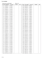
Page 46: ...31 2SA1493 PY F1 TRANSISTOR A 2 Q763 Q764 32 2SD2390LD OPY TRANSISTOR A 1 Q1751 2SD2390LD OPY TRANSISTOR A 2 Q1851 Q1852 33 2SB1560LD OPY TRANSISTOR A 1 Q1752 2SB1560LD OPY TRANSISTOR A 2 Q1853 Q1854 34 E73525 003SS SCREW 14 TR 35 LV41603 001A LEAF SPRING 1 36 LV20035 001A H S BRACKET R 1 37 LV20036 001A H S BRACKET L 1 38 QYSBSGG3008E T SCREW 17 39 VKZ4150 001 SPECIAL NUT 1 40 QQT0302 001 POWER T...

Page 47: ... E CAPACITOR 4 7MF 20 50V C 821 QEHR1EM 107Z E CAPACITOR 100MF 20 25V C 822 QCF31HZ 472Z C CAPACITOR 4700PF 80 20 C 831 QEHR1EM 107Z E CAPACITOR 100MF 20 25V C 832 QCF31HZ 472Z C CAPACITOR 4700PF 80 20 C 841 QEHR1EM 107Z E CAPACITOR 100MF 20 25V C 842 QCF31HZ 472Z C CAPACITOR 4700PF 80 20 C 851 QEHR1EM 107Z E CAPACITOR 100MF 20 25V C 852 QCF31HZ 472Z C CAPACITOR 4700PF 80 20 C 861 QEHR1EM 107Z E C...

Page 48: ...DIODE A D 822 1SS133 T2 SI DIODE D 831 MTZJ6 2C T2 Z DIODE A D 832 1SS133 T2 SI DIODE D 841 MTZJ6 2C T2 Z DIODE A D 842 1SS133 T2 SI DIODE D 851 MTZJ15C T2 Z DIODE A D 852 1SS133 T2 SI DIODE D 861 MTZJ15C T2 Z DIODE A D 862 1SS133 T2 SI DIODE D 871 MTZJ10C T2 Z DIODE A D 872 1SS133 T2 SI DIODE D 901 1SS133 T2 SI DIODE D 902 1SS133 T2 SI DIODE D 921 MTZJ4 7B T2 Z DIODE D 931 1SS133 T2 SI DIODE D 93...

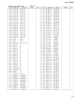
Page 49: ...2K 5 1 4W R 906 QRE141J 123Y C RESISTOR 12K 5 1 4W R 909 QRE141J 103Y C RESISTOR 10K 5 1 4W R 911 QRE141J 332Y C RESISTOR 3 3K 5 1 4W R 912 QRE141J 473Y C RESISTOR 47K 5 1 4W R 913 QRE141J 104Y C RESISTOR 100K 5 1 4W R 914 QRE141J 823Y C RESISTOR 82K 5 1 4W R 915 QRE141J 823Y C RESISTOR 82K 5 1 4W R 916 QRE141J 563Y C RESISTOR 56K 5 1 4W R 917 QRE141J 683Y C RESISTOR 68K 5 1 4W R 918 QRE141J 822Y ...

Page 50: ...C RESISTOR 1 0K 5 1 4W R1406 QRE141J 474Y C RESISTOR 470K 5 1 4W R1411 QRE141J 102Y C RESISTOR 1 0K 5 1 4W R1412 QRE141J 103Y C RESISTOR 10K 5 1 4W R1421 QRE141J 102Y C RESISTOR 1 0K 5 1 4W R1422 QRE141J 102Y C RESISTOR 1 0K 5 1 4W R1423 QRE141J 103Y C RESISTOR 10K 5 1 4W R1424 QRE141J 103Y C RESISTOR 10K 5 1 4W R1435 QRE141J 683Y C RESISTOR 68K 5 1 4W R1436 QRE141J 104Y C RESISTOR 100K 5 1 4W R14...

Page 51: ...APACITOR 47MF 20 25V C1469 QCS11HJ 470 C CAPACITOR 47PF 5 50V C1470 QCS11HJ 470 C CAPACITOR 47PF 5 50V C1471 QFVJ1HJ 333Z CAPACITOR 033MF 5 50V C1472 QFVJ1HJ 333Z CAPACITOR 033MF 5 50V C1473 QER41HM 105 E CAPACITOR 1 0MF 20 50V C1474 QER41HM 105 E CAPACITOR 1 0MF 20 50V C1475 QFLC1HJ 332Z M CAPACITOR 3300PF 5 50V C1476 QFLC1HJ 332Z M CAPACITOR 3300PF 5 50V C1477 QFVJ1HJ 104Z TF CAPACITOR 10MF 5 50...

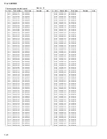
Page 52: ...10K 5 1 4W R 478 QRE141J 103Y C RESISTOR 10K 5 1 4W R 479 QRE141J 102Y C RESISTOR 1 0K 5 1 4W R 480 QRE141J 221Y C RESISTOR 220 5 1 4W R 481 QRE141J 221Y C RESISTOR 220 5 1 4W R 482 QRE141J 221Y C RESISTOR 220 5 1 4W R 483 QRE141J 473Y C RESISTOR 47K 5 1 4W R 484 QRE141J 331Y C RESISTOR 330 5 1 4W R 485 QRE141J 221Y C RESISTOR 220 5 1 4W R 487 QRE141J 331Y C RESISTOR 330 5 1 4W R 488 QRE141J 331Y ...

Page 53: ... 415 QSW0683 001Z PUSH SWITCH S SELECT S 416 QSW0683 001Z PUSH SWITCH TUNING S 417 QSW0683 001Z PUSH SWITCH PRESET S 418 QSW0683 001Z PUSH SWITCH MEMORY S 419 QSW0683 001Z PUSH SWITCH SETTING S 420 QSW0683 001Z PUSH SWITCH OTO X 400 QAX0112 001Z RESONATOR X 401 QAX0246 001Z RESONATOR Front board ...

Page 54: ...APACITOR 47MF 20 25V C 317 QETN1HM 226Z E CAPACITOR 22MF 20 50V C 318 QETN1HM 226Z E CAPACITOR 22MF 20 50V C 319 QCF31HZ 223Z C CAPACITOR 022MF 80 20 C 320 QCF31HZ 223Z C CAPACITOR 022MF 80 20 C 321 QETN1HM 226Z E CAPACITOR 22MF 20 50V C 322 QETN1HM 226Z E CAPACITOR 22MF 20 50V C 323 QCS31HJ 331Z C CAPACITOR 330PF 5 50V C 324 QCS31HJ 331Z C CAPACITOR 330PF 5 50V C 325 QCS31HJ 331Z C CAPACITOR 330P...

Page 55: ...J 750Y C RESISTOR 75 5 1 4W R 248 QRE141J 151Y C RESISTOR 150 5 1 4W R 249 QRE141J 121Y C RESISTOR 120 5 1 4W R 256 QRE141J 472Y C RESISTOR 4 7K 5 1 4W R 257 QRE141J 471Y C RESISTOR 470 5 1 4W R 258 QRE141J 472Y C RESISTOR 4 7K 5 1 4W R 259 QRE141J 471Y C RESISTOR 470 5 1 4W R 264 QRE141J 103Y C RESISTOR 10K 5 1 4W R 265 QRE141J 103Y C RESISTOR 10K 5 1 4W R 266 QRE141J 750Y C RESISTOR 75 5 1 4W R ...

Page 56: ...70 5 1 4W R 362 QRE141J 471Y C RESISTOR 470 5 1 4W R 381 QRE141J 183Y C RESISTOR 18K 5 1 4W R 382 QRE141J 102Y C RESISTOR 1 0K 5 1 4W R 383 QRE141J 104Y C RESISTOR 100K 5 1 4W R 384 QRE141J 104Y C RESISTOR 100K 5 1 4W R 385 QRE141J 471Y C RESISTOR 470 5 1 4W R 386 QRE141J 471Y C RESISTOR 470 5 1 4W R 387 QRE141J 103Y C RESISTOR 10K 5 1 4W R 388 QRE141J 103Y C RESISTOR 10K 5 1 4W R1250 QRE141J 101Y...

Page 57: ...N953 QGA3901C1 06 6P PLUG ASSY C1701 QETN1HM 106Z E CAPACITOR 10MF 20 50V C1702 QCS11HJ 470 C CAPACITOR 47PF 5 50V C1703 QCS11HJ 221 C CAPACITOR 220PF 5 50V C1704 QETN1EM 476Z E CAPACITOR 47MF 20 25V C1705 QCS11HJ 100 C CAPACITOR 10PF 5 50V C1711 QCS32HJ 330Z C CAPACITOR 33PF 5 500V C1712 QFLC1HJ 103Z M CAPACITOR 010MF 5 50V C1713 QETN1HM 225Z E CAPACITOR 2 2MF 20 50V C1715 QETN1HM 476Z E CAPACITO...

Page 58: ... BL AB T TRANSISTOR Q1703 2SA1038S S T TRANSISTOR Q1731 2SD637 QR TRANSISTOR Q1771 2SC2389S SE T TRANSISTOR Q1772 2SA1038S SE T TRANSISTOR Q1791 2SC2389S SE T TRANSISTOR Q1801 2SC2240 BL AB T TRANSISTOR Q1802 2SC2240 BL AB T TRANSISTOR Q1803 2SC2240 BL AB T TRANSISTOR Q1804 2SC2240 BL AB T TRANSISTOR Q1805 2SA1038S S T TRANSISTOR Q1806 2SA1038S S T TRANSISTOR Q1831 2SD637 QR TRANSISTOR Q1832 2SD63...

Page 59: ...K 5 1 4W R1805 QRE141J 202Y C RESISTOR 2 0K 5 1 4W R1806 QRE141J 202Y C RESISTOR 2 0K 5 1 4W R1809 QRE141J 123Y C RESISTOR 12K 5 1 4W R1810 QRE141J 123Y C RESISTOR 12K 5 1 4W R1811 QRE141J 911Y C RESISTOR 910 5 1 4W R1812 QRE141J 911Y C RESISTOR 910 5 1 4W R1813 QRE141J 104Y C RESISTOR 100K 5 1 4W R1814 QRE141J 104Y C RESISTOR 100K 5 1 4W R1821 QRJ146J 221X UNF C RESISTOR A 220 5 1 4W R1822 QRJ146...

Page 60: ...696 NEA71HM 105X E CAPACITOR C 697 NEA71HM 105X E CAPACITOR C 698 NEA71HM 105X E CAPACITOR CN681 QGB1214K3 18W CONNECTOR CN687 QGB1214K3 12W CONNECTOR C2500 NEA71CM 226X E CAPACITOR C2501 NCB31AK 474X C CAPACITOR C2503 NEA71EM 475X E CAPACITOR C2504 NEA71EM 475X E CAPACITOR C2505 NCS31HJ 560X C CAPACITOR C2506 NCS31HJ 560X C CAPACITOR C2507 NCS31HJ 560X C CAPACITOR C2508 NCS31HJ 560X C CAPACITOR C...

Page 61: ...K 601 NQR0269 007X FERRITE BEADS K 611 NQR0269 007X FERRITE BEADS K 612 NQR0269 007X FERRITE BEADS K 613 NQR0269 007X FERRITE BEADS K 614 NQR0269 007X FERRITE BEADS K 615 NQR0269 007X FERRITE BEADS K 616 NQR0269 007X FERRITE BEADS K 617 NQR0269 007X FERRITE BEADS K 618 NQR0269 007X FERRITE BEADS K 619 NQR0269 007X FERRITE BEADS K 620 NQR0269 007X FERRITE BEADS K 621 NQR0269 007X FERRITE BEADS K 62...

Page 62: ...20 NRSA63J 102X MG RESISTOR R2521 NRSA63J 102X MG RESISTOR R2522 NRSA63J 102X MG RESISTOR R2523 NRSA63J 102X MG RESISTOR R2524 NRSA63J 102X MG RESISTOR R2525 NRSA63J 102X MG RESISTOR R2526 NRSA63J 102X MG RESISTOR R2527 NRSA63J 104X MG RESISTOR R2528 NRSA63J 104X MG RESISTOR R2529 NRSA63J 103X MG RESISTOR R2530 NRSA63J 103X MG RESISTOR R2531 NRSA63J 113X MG RESISTOR R2532 NRSA63J 113X MG RESISTOR ...

Page 63: ...5 A R2595 NRSA63J 102X MG RESISTOR R2596 NRSA63J 102X MG RESISTOR R2597 NRSA63J 104X MG RESISTOR R2598 NRSA63J 104X MG RESISTOR UN661 GP1FA550RZ OPT RECEIVER UN662 GP1FA550RZ OPT RECEIVER UN663 GP1FA550TZ OPT TRANSMITTER X 631 NAX0385 001X CRYSTAL X 671 NAX0275 001X C OSCIALLATOR AC 3 board ...

Page 64: ... CAPACITOR 10MF 20 16V CF101 QAX0285 001Z C FILTER CF102 QAX0285 001Z C FILTER CF103 QAX0519 001Z C FILTER CN111 QGB2501K2 12 CONECTOR CN112 QGB2501K1 04 CONNECTOR D 121 1SS133 T2 SI DIODE D 123 1SS133 T2 SI DIODE D 129 1SS133 T2 SI DIODE D 131 1SS133 T2 SI DIODE IC102 LA1838 IC IC121 LC72136N IC IC191 SAA6588 IC RDS L 112 QQL231K 2R7Y INDUCTOR Q 102 2SC535 BC T TRANSISTOR Q 103 2SC461 BC T TRANSI...

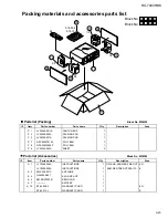
Page 65: ... PAD 1 P 3 LV20040 001A PACKING PAD 1 P 7 QPC06507015P POLY BAG 1 P 8 QPA02503505P POLY BAG 1 P 9 LV32034 003A SHEET 2 Packing Item Parts number Parts name Area A Parts list Q ty Description Block No M3MM A 1 LVT0396 006A INSTRUCTIONS EN 1 LVT0396 005A INSTRUCTIONS E 1 A 3 EWP503 001C ANT WIRE 1 A 4 QAL0204 001 AM LOOP ANT 1 A 6 RM SRX7000R REMOCON 1 A 7 BATTERY 1 A 10 BT 54008 2 WARRANTY CARD EN ...

Page 66: ... 7000RBK Printed in Japan 2000 07 O No 20846 RX 7000RBK VICTOR COMPANY OF JAPAN LIMITED AUDIO COMMUNICATION BUSINESS DIVISION PERSONAL MOBILE NETWORK B U 10 1 1Chome Ohwatari machi Maebashi city 371 8543 Japan ...

Page 67: ... MD TV DBS PHONO FM AM VCR ANALOG DIGITAL SURROUND CENTER SURROUND TEST REAR L CD DISC MODE ON OFF EFFECT REAR R SOUND SEA MODE SUBWOOFER RETURN SET MENU AUDIO TV VCR EXIT TEXT DISPLAY SLEEP 1 2 3 4 5 6 7 P 8 9 10 0 10 100 FM MODE CATV DBS MENU MENU ENTER ENTER TV CATV DBS VCR PTY SEARCH PTY PTY RX 7000R AUDIO VIDEO CONTROL RECEIVER STANDBY SPEAKERS 1 2 PHONES SURROUND ON OFF DSP MODE BALANCE SURR...

Page 68: ...mmutateurSTANDBY ON necoupejamaiscomplètementla ligne de secteur quelle que soit sa position Le courant peut être télécommandé Voorzichtig STANDBY ON schakelaar Om de stroomtoevoer geheel uit te schakelen trekt u de stekker uit het stopkontakt Anders zal er altijd een geringe hoeveelheid stroom naar het apparaat lopen ongeacht de stand van de STANDBY ON schakelaar U kunt het apparaat ook met de af...

Page 69: ...ns 10 cm aan weerszijden vrij houden Bovenkant Niets bovenop plaatsen 10 cm speling geven Achterkant Minstens 15 cm ruimte achteraan vrij houden Onderkant Opstellen op een egaal horizontaal oppervlak Bovendien moet er rondom voldoende luchtdoorstroming zijn zoals in de afbeelding aangegeven Precaución Ventilación Adecuada Para evitar el riesgo de choque eléctrico e incendio y para proteger el apar...

Page 70: ...ng to a Broadcast Program of Your Choice Temporarily 23 Using the SEA Modes 24 SelectingYour Favorite SEA Mode 24 Creating Your Own SEA Mode 24 Using the DSP Modes 25 Available DSP Modes According to the Speaker Arrangement 27 Adjusting the 3D PHONIC Modes 28 Adjusting the DAP Modes 28 Adjusting the Surround Modes 29 Activating the DSP Modes 31 Using the DVD MULTI Playback Mode 33 Activating the D...

Page 71: ...1 u CHANNEL buttons 47 49 i VOLUME buttons 11 o MUTING button 12 Front Panel 1 STANDBY ON button and STANDBY lamp 10 2 Remote sensor 9 3 SURROUND ON OFF button and lamp 30 31 4 SEA MODE button 24 5 INPUT ANALOG DIGITAL button 16 6 FM AM TUNING button 19 7 FM MODE button 20 8 Display 10 9 Source lamps 10 p MASTER VOLUME control 11 q PHONES jack 12 w SPEAKERS 1 2 buttons and lamps 11 e RDS operation...

Page 72: ... screws covers or cabinet Do not expose the receiver to rain or moisture Checking the Supplied Accessories Check to be sure you have all of the following items which are supplied with the receiver The number in the parentheses indicates quantity of the pieces supplied Remote Control 1 Batteries 2 AM MW LW Loop Antenna 1 FM Antenna 1 If anything is missing contact your dealer immediately A Using th...

Page 73: ...e AM MW LW loop antenna connected Connecting the Speakers You can connect the following speakers Two pairs of front speakers to produce normal stereo sound One pair of rear speakers to enjoy the surround effect One center speaker to produce more effective surround effect to emphasize human voices One subwoofer to enhance the bass IMPORTANT After connecting the speakers listed above set the speaker...

Page 74: ...ce such as a graphic equalizer between the source components and this receiver the sound output through this receiver may be distorted RIGHT LEFT TAPE MD IN PLAY OUT REC CD PHONO AUDIO Turntable To audio output Turntable If an earth cable is provided for your turntable connect the cable to the screw marked H on the rear panel Connecting the rear and center speakers Connect rear speakers to the REA...

Page 75: ...ks When connecting an MD recorder to the TAPE MD jacks change the source name which will be shown on the display when selected as the source to MD See page 13 for details If your audio components have a COMPU LINK 3 or TEXT COMPU LINK jack See also page 39 for detailed information about the connection and the COMPU LINK 3 remote control system See also page 40 for detailed information about the co...

Page 76: ...ut Î To front left right channel audio output To rear left right channel audio output Ï To composite video output DVD player Note When connecting the DBS tuner to the TV SOUND DBS jacks change the source name which will be shown on the display when selected as the source to DBS See page 13 for details DBS RIGHT VIDEO VIDEO S VIDEO RIGHT LEFT AUDIO IN PLAY OUT REC IN PLAY OUT REC TV SOUND DBS DVD V...

Page 77: ...lug DVD player DBS tuner When the component has a digital optical output terminal connect it to the DIGITAL 2 CD or DIGITAL 3 TV terminal using the digital optical cable not supplied When the component has a digital coaxial output terminal connect it to the DIGITAL 1 DVD terminal using the digital coaxial cable not supplied Digital coaxial cable not supplied between digital coaxial terminals Digit...

Page 78: ...he cord always grasp the plug so as not to damage the cord Putting Batteries in the Remote Control Before using the remote control put two supplied batteries first When using the remote control aim the remote control directly at the remote sensor on the receiver 1 On the back of the remote control remove the battery cover 2 Insert batteries Make sure to match the polarity to 3 Replace the cover If...

Page 79: ... SOUND or DBS O VCR O back to the beginning The selected source lamp also lights up The DVD lamp lights up both for DVD and DVD MULTI From the remote control Press one of the source selecting buttons DVD DVD MUILTI CD TAPE MD TV DBS PHONO FM AM VCR Selected source name appears DVD Select the DVD player DVD MULTI Select the DVD player for viewing the digital video disc using the analog discrete out...

Page 80: ...PE MD PHONO FM AM TV DBS while viewing the picture from a video component such as the VCR or DVD player etc Notes Once you have selected a video source pictures of the selected source are sent to the TV until you select another video source The TV DBS button only works for selecting DBS as the source but not for selecting TV SOUND When you use the DBS tuner change the source name correctly see pag...

Page 81: ...OOST ON and off BASSBOOST OFF Select BASSBOOST ON to activate the bass boost function The BASS BOOST indicator lights up on the display Select BASSBOOST OFF to cancel it The indicator goes off Note This function affects the front speaker sounds only Attenuating the Input Signal When the input level of the playing source is too high the sounds will be distorted If this happens you need to attenuate...

Page 82: ...TI JOG to register whether you have connected a subwoofer or not As you turn it the subwoofer setting alternates between YES and NO YES Select this when a subwoofer is used SUBWFR lights up on the display see page 11 NO Select this when no subwoofer is used MULTI JOG SOURCE SELECTOR BASS BOOST SOURCENAME SETTING MULTI JOG IMPORTANT When using the remote control check to see if its remote control m...

Page 83: ...Turn it clockwise to increase the delay time from 0 msec R DELAY 0ms to 15 msec R DELAY 15ms Turn it counterclockwise to decrease the delay time from 15 msec R DELAY 15ms to 0 msec R DELAY 0ms Notes Rear delay time setting is not valid for the DVD MULTI playback mode You cannot adjust the rear delay time when you have set REAR SPK to NONE Setting the Speakers for the DSP Modes To obtain the best p...

Page 84: ...while playing back a source using Dolby Digital DTS Digital Surround or MPEG Multichannel follow the procedure below On the front panel ONLY 1 Press SETTING repeatedly until LFE ATT Low Frequency Effect Attenuator appears on the display The display changes to show the current setting 80Hz 100Hz 120Hz 2 Turn MULTI JOG to select the low frequency effect attenuator level As you turn it the display ch...

Page 85: ...ator for the detected signal lights up automatically When the receiver cannot recognize the incoming signal format correctly the frame of the digital signal indicator flashes If this happens select the same digital input mode with the incoming digital signal DOLBY DIGITAL DTS or MPEG To change the input mode back to analog input select ANALOG Digital Input DIGITAL IN Terminal Setting When you use ...

Page 86: ...recorder or CD player equipped with TEXT COMPU LINK remote control system see page 40 you can show the text information such as disc title or track title on the display of this receiver To show it on the display follow the procedure below Before you start remember There is a time limit in doing the following steps If the setting is canceled before you finish start from step 1 again On the front pa...

Page 87: ... settings for the currently selected source are recalled when the source is selected To cancel the One Touch Operation function Press ONE TOUCH OPERATION so that the lamp goes off Even though the One Touch Operation function is canceled the recalled sound effects remain active Notes If the source is FM or AM MW LW you can assign a different setting for each band The DSP modes and DVD MULTI playbac...

Page 88: ...stops flashing The station is assigned to the selected channel number 5 Repeat steps 1 to 4 until you store all the stations you want To erase a stored preset station Storing a new station on a used number erases the previously stored one Receiving Radio Broadcasts You can browse through all the stations or use the preset function to go immediately to a particular station AUDIO TV VCR CATV DBS TUN...

Page 89: ...e stations The AUTO MUTING indicator goes off on the display SOURCE SELECTOR TUNER PRESET MULTI JOG Note When using the FM MODE button on the remote control be sure that the 10 keys are activated for the tuner not for the CD and others See page 45 Assigning Names to Preset Stations You can assign a name of up to four characters to each preset station When a preset station is tuned in its assigned ...

Page 90: ...end their station names as well as information about what type of program they broadcast such as sports or music etc When tuned to an FM station which provides the RDS service the RDS indicator lights up on the display With the receiver you can receive the following types of RDS signals PS Program Service Shows commonly known station names PTY Program Type Shows types of broadcast programs RT Radi...

Page 91: ...tation To continue searching after the first stop Press PTY SEARCH again while the indications on the display are flashing If no program is found NOTFOUND appears on the display From the remote control 1 Press PTY SEARCH while listening to an FM station PTY SELECT flashes on the display 2 Press and hold PTY until the PTY code you want appears on the display while PTY SELECT is flashing The display...

Page 92: ...have selected the receiver automatically switches to the station The indicator of received PTY code starts flashing When the program is over the receiver goes back to the previously selected source but still remains in EON standby mode The indicator of received PTY code stops flashing and remains lit If the FM station you are listening to is broadcasting the program you have selected The receiver ...

Page 93: ...ears The SEA indicator goes off from the display From the remote control 1 Press SOUND The 10 keys are activated for sound adjustments 2 Press SEA MODE repeatedly until the SEA mode you want appears on the display To cancel the SEA mode Press SEA MODE repeatedly until SEA OFF appears in step 2 above The SEA indicator goes off from the display AUDIO TV VCR CATV DBS SEA MODE SOUND SEA MODE RETURN 10...

Page 94: ...AR SPK and CENTER SPK are set to NONE see page 14 DAP modes The sound heard in a concert hall or club consists of direct sound and indirect sound early reflections and reflections from behind Direct sounds reach the listener directly without any reflection On the other hand indirect sounds are delayed by the distances of the ceiling and walls These direct sounds and indirect sounds are the most im...

Page 95: ... Digital enables stereo rear sounds and sets the cutoff frequency of the rear treble at 20 kHz comparing to 7 kHz for Dolby Pro Logic These facts enhance the sound movement and being there feelings much more than Dolby Pro Logic To enjoy the software encoded with Dolby Digital you must connect the source component using the digital terminal on the rear of this receiver See page 8 DTS Digital Surro...

Page 96: ...DTS MPEG SURROUND DOLBY PRO LOGIC DOLBY DIGITAL DTS SURROUND or MPEG SURROUND THEATER LIVE CLUB DANCE CLUB HALL PAVILION 3D ACTION DSP OFF DSP mode is canceled Activated automatically only when AUTO PCM is selected as the digital input and playback source is encoded with Dolby Digital Activated automatically only when AUTO PCM is selected as the digital input and playback source is encoded with DT...

Page 97: ...UDIO TV VCR CATV DBS DSP MODE DSP EFFECT 1 DSP EFFECT 2 DSP EFFECT 3 DSP EFFECT 4 DSP EFFECT 5 EFFECT 7 P MULTI JOG BALANCE SURROUND ADJUST BALANCE SURROUND ADJUST IMPORTANT When using the remote control check to see if its remote control mode selector is set to the correct position To operate this receiver set it to AUDIO TV VCR Adjusting the 3D PHONIC Modes Once you have adjusted the 3D PHONIC m...

Page 98: ... the effect level changes as follows As the number increases the selected DAP mode becomes stronger From the remote control 1 Press SURROUND MODE repeatedly until the DAP mode LIVE CLUB DANCE CLUB HALL or PAVILION appears on the display The DSP indicator also lights up on the display When you have set REAR SPK to NONE the 3D PHONIC indicator also lights up 2 Press SOUND The 10 keys are activated f...

Page 99: ...om 10 dB to 10 dB On the front panel You can also use the buttons on the front panel to adjust the Surround modes However no test tone is available when using the buttons on the front panel So make adjustments while listening to the sound of the source played back 1 Press SURROUND ON OFF to activate an appropriate Surround mode PRO LOGIC DOLBY DIGITAL DTS SURROUND or MPEG SURROUND Each time you pr...

Page 100: ...on the front panel to adjust the Surround modes However no test tone is available when using the buttons on the front panel So make adjustments while listening to the sound of the source played back 1 Press DSP MODE repeatedly until THEATER appears on the display The Ÿ PRO LOGIC and DSP indicators also light up on the display 2 Adjust the speaker output levels 1 Press BALANCE SURROUND ADJUST repea...

Page 101: ...nge 2 Select and play a sound source To enjoy 3D PHONIC and JVC Theater Surround play back a software encoded with Dolby Surround and labeled with DOLBY SURROUND mark To cancel the DSP mode Press SURROUND MODE repeatedly until DSP OFF appears on the display Note While playing back MPEG Multichannel or Dolby Digital source through a digital input terminal you can neither select nor adjust any DSP m...

Page 102: ...yback mode while playing back a DVD using the analog discrete output mode on the DVD player Once you have made adjustments the receiver memorizes the adjustments until you change them You also need to set the DVD player to the analog discrete output mode Before you start remember There is a time limit in doing the following steps If the setting is canceled before you finish start from step 1 again...

Page 103: ... fi buttons also displays the MAIN MENU 2 Press fi to move to MODE 3 Press to select the DSP mode you want to use 4 When you finish press EXIT The menu disappears from the TV Selecting the Analog or Digital Input Mode Also see page 16 This selection is only possible when the digital input DIGITAL IN terminal setting has been correctly done for the digital source currently selected 1 Press MENU The...

Page 104: ...The SOUND CONTROL menu appears 3 Press fi to move to SUBWFR LEVEL 4 Press to adjust the subwoofer output level 5 When you finish press EXIT repeatedly until the menu disappears from the TV Adjusting the DSP Modes Also see pages 28 31 1 Press MENU The MAIN MENU appears on the TV Pressing one of the fi buttons also displays the MAIN MENU 2 Press fi to move to MODE 3 Press to select the DSP mode you ...

Page 105: ...he effect level For Dolby Pro Logic TEST TONE Output a test tone CENTER LEVEL Adjust the center speaker output level REAR L LEVEL Adjust the left rear speaker output level REAR R LEVEL Adjust the right rear speaker output level For Dolby Digital DTS Digital Surround and MPEG Multichannel TEST TONE Output a test tone CENTER LEVEL Adjust the center speaker output level REAR L LEVEL Adjust the left r...

Page 106: ... SETTING 1 SUBWOOFER NO FRONT SPK LARGE CENTER SPK SMALL REAR SPK LARGE CNTR DELAY 3msec REAR DELAY 5msec CROSSOVER 100Hz NEXT PAGE ENTER SETTING 2 LFE ATT 0dB COMP MID DIGITAL 1 DVD DIGITAL 2 CD DIGITAL 3 TV FL DISP NORMAL PREVIOUS PAGE ENTER LFE ATT Set the low frequency effect attenuator level see page 15 COMP Set the dynamic range compression see page 15 DIGITAL 1 2 3 Set the digital input ter...

Page 107: ...NER CONTROL then press The TUNER CONTROL menu appears 3 Tune into a station on the TUNER CONTROL menu referring to Operating the Tuner on the previous page 4 Press fi to move to PRESET MEMORY then press The PRESET MEMORY menu appears 5 Press to select a preset station number you want 6 Press SET to store the setting 7 When you finish press EXIT repeatedly until the menu disappears from the TV Assi...

Page 108: ...m The COMPU LINK remote control system allows you to operate JVC audio components through the remote sensor on the receiver Turntable CD player Cassette deck or MD recorder COMPU LINK 3 SYNCHRO Automatic Power On Off Standby only possible with the COMPU LINK 3 connection Both the CD player and cassette deck or MD recorder turn on and off standby along with the receiver When you turn on the receive...

Page 109: ... in the series of components For example the CD player in the diagram to the left TEXT COMPULINK SOURCE NOT CONNECTED appears on the display in the following cases When the connections explained to the left are not correctly done When you try to use the TEXT COMPU LINK function a few seconds after you turn on the connected equipment This is not a malfunction of the units Refer also to the manuals ...

Page 110: ...example the SET button will be used to start play PLAY to go to the next screen ENTER and to determine the selection ENTER To exit from the Disc information screen Press EXIT Notes The on screen display will disappear in the following cases if no operation is done for about 10 minutes if you do any operation other than explained in this section To control the MD recorder using the TEXT COMPU LINK ...

Page 111: ...l they appear Going back to the DISC TITLE SEARCH screen Press EXIT Searching for a Disc Only for the CD player Search for a disc by its performer 1 Press TEXT DISPLAY while CD is selected as the source The Disc Information screen appears on the TV 2 Press fi to move to SEARCH then press SET The DISC SEARCH screen appears 3 Press fi to move to PERFORMER then press SET The PERFORMER SEARCH screen a...

Page 112: ... with the disc memory function You can use the disc memory function through this receiver The disc information its performer disc title and music genre of normal audio CDs will be stored into the memory built in the CD player For the disc memory function refer to the manual supplied with your CD player The performer disc title and music genre information are usually recorded in a CD Text However i...

Page 113: ...itle for the song currently selected indicated in yellow on the TV screen 5 Enter the song title referring to steps 3 and 4 of For the CD Player with the disc memory function on page 43 You can enter up to 32 characters for the song title 6 Press fi to move to the song title you have just entered then press SET The song title is stored into the memory and the Disc Information screen appears again ...

Page 114: ...tput level CENTER Adjusts the center speaker output level REAR L Adjusts the left rear speaker output level REAR R Adjusts the right rear speaker output level EFFECT Selects the effect level TEST Turns on or off the test tone output Note After adjusting sounds press the corresponding source selecting button or CD DISC to operate your target source by using the 10 keys otherwise the 10 keys cannot ...

Page 115: ...er TAPE MD button or the TAPE MD CONTROL button to activate the buttons listed above If you press TAPE MD the playing source also changes On the other hand if you press TAPE MD CONTROL the playing source does not change CD player changer After pressing CD DISC with the remote control mode selector set to AUDIO TV VCR you can perform the following operations on a CD player changer PLAY Starts playi...

Page 116: ...tor set to AUDIO TV VCR you can perform the following operations on a DVD player PLAY Starts playing 4 Returns to the beginning of the current or previous track Skips to the beginning of the next track STOP Stops playing PAUSE Stops playing temporarily To release it press PLAY After pressing DVD or DVD MULTI these buttons can be used for the DVD menu operations Note For detailed menu operations re...

Page 117: ...OFER RETURN SET MENU AUDIO TV VCR EXIT TEXT DISPLAY FM MODE SLEEP 1 2 3 4 5 6 7 P 8 9 10 0 10 100 CATV DBS MENU ENTER To change the transmittable signals for operating another manufacturer s TV 1 Set the remote control mode to AUDIO TV VCR 2 Press and hold TV CATV DBS 3 Press TV DBS 4 Enter manufacturer s code three digits using buttons 1 9 and 0 See the list on pages 50 and 51 to find the code Ex...

Page 118: ...CR 1 Set the remote control mode to AUDIO TV VCR 2 Press and hold VCR 3 Press VCR 4 Enter manufacturer s code three digits using buttons 1 9 and 0 See the list on pages 52 and 53 to find the code Examples For a JVC product press 0 0 then 8 For an NEC product press 0 3 then 8 5 Release VCR The following button can be used for operating the VCR with the remote control mode selector set to AUDIO TV V...

Page 119: ...480 Magnadyne 087 102 247 516 Magnafon 076 102 213 516 Manesth 217 235 264 320 Marantz 037 556 Marelli 087 Mark 037 Matsui 009 011 035 036 037 072 177 208 211 217 235 294 354 355 371 443 487 516 579 Manufacturers codes for TV Acura 009 Admiral 087 163 213 Adyson 032 217 AGB 516 Akai 208 361 516 Akura 218 264 369 Alba 009 036 037 211 218 235 371 Allorgan 294 Amplivision 217 400 Amstrad 009 037 171 ...

Page 120: ...chael 043 Mediator 012 037 Memorex 009 Memphis 337 Metz 087 213 367 535 Minerva 070 487 535 554 Minoka 369 412 Mitsubishi 036 087 108 150 201 354 512 535 Mivar 216 290 291 292 516 Motion 076 MTC 349 512 Multitech 009 076 102 216 Neckermann 037 087 191 213 349 505 554 556 NEI 037 337 431 Nesco 179 Nikkai 032 035 037 072 216 218 264 337 Nobliko 076 102 Nokia 361 480 548 Nordmende 109 196 198 213 287...

Page 121: ...adix 396 RFT 200 220 288 Saba 336 520 Sabre 455 Salora 108 Manufacturers codes for CATV converters Brigminghan Cable Communications 276 British Telecom 003 105 Decsat 423 Filmnet 443 France Telecom 451 Jerrold 003 276 MNet 443 PVP Stereo Visual Matrix 003 Salora 382 Scientific Atlanta 008 277 Tele 1 443 United Cable 003 Westminster 105 Zenith 000 Manufacturers codes for VCR Aiwa 000 307 348 352 Ak...

Page 122: ...Ferguson 041 084 098 107 320 321 Fidelity 000 Finlandia 081 104 Finlux 000 042 081 104 105 Firstline 037 043 045 072 209 Fisher 046 047 054 104 Frontech 020 Funai 000 GEC 081 General 020 GoldHand 072 GoldStar 037 225 Goodmans 000 020 037 072 278 403 Graetz 005 041 104 240 344 Granada 046 081 104 Grandin 000 037 072 Grundig 003 006 007 016 072 081 195 207 226 347 349 403 Hanseatic 037 HCM 072 Hinar...

Page 123: ...re overloaded because of short circuit of speaker terminals The remote control mode selector is not set correctly There is an obstruction in front of the remote sensor on the receiver Batteries are weak SOLUTION Plug the power cord into an AC outlet Check speaker wiring and reconnect if necessary Press SPEAKERS 1 and 2 correctly Select the correct source Press MUTING to cancel the mute Check speak...

Page 124: ...inear PCM Dolby Digital DTS Digital Surround and MPEG Multichannel with sampling frequency 32 kHz 44 1 kHz 48 kHz Audio Output Level TAPE MD VCR 200 mV Digital output Optical DIGITAL OUTPUT Signal wave length 660 nm Output level 21 dBm to 15 dBm Signal to Noise Ratio 66 IHF DIN PHONO 70 dB 66 dB at REC OUT CD TAPE MD TV SOUND DBS VCR DVD 87 dB 67 dB Frequency Response 8 Ω PHONO 20 Hz to 20 kHz 1 d...

Page 125: ...t REC OUT 35 dB at 1 kHz Alternate Channel Selectivity 60 dB 400 kHz Frequency Response 30 Hz to 15 kHz 0 5 dB 3 dB AM MW LW tuner Tuning Range MW 522 kHz to 1 629 kHz LW 144 kHz to 288 kHz Usable Sensitivity Loop antenna 400 µV m Signal to Noise Ratio 50 dB 100 mV m General Power Requirements AC 230 V 50 Hz Power Consumption 210 W at operation 2 W in standby mode Dimensions W x H x D 435 mm x 157...

Page 126: ...VICTOR COMPANY OF JAPAN LIMITED EN GE FR NL SP IT J VC 0400HIMMDWJEIN RX 7000R E COVER f 00 4 25 0 01 PM 2 ...

Reviews: