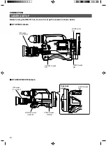
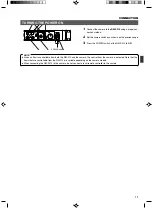
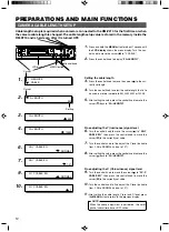
background image

14

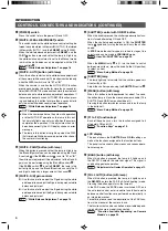
The intercom employs the RTS system.
If it is required to change this to a 2-wire system, consult your
nearest JVC-authorized service agent. (The modification will
then be carried out with charge.)
An intercom jack is provided on the front panel of the 

RM-P210.

The volume level of the headset’s earphone can be adjusted
using the 

INTERCOM LEVEL

 control.

INTERCOM

Intercommunications between operators are necessary in a system composed of multiple cameras
and remote control units.

PREPARATIONS AND MAIN FUNCTIONS

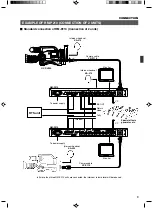
When the 

CALL

 button is pressed, the button lamp is lit and

the tally lamp on the camera blinks. Pressing the button again
turns off both the button lamp and the blinking of the camera’s
tally lamp.

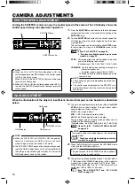
CAMERA OPERATOR CALL

This function makes it possible to call the camera operator without using the intercom. The camera
operator is informed of the call by the blinking of the tally lamp on the camera.

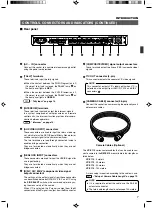
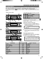
The 

TALLY

  lamp lights in 

red

  when contact is made be-

tween the PGM (Program) and C (Common) terminals.

The 

TALLY

 lamp lights in 

green

 when contact is made be-

tween the PVW (Preview) and C (Common) terminals.

TALLY INPUT

The TALLY lamp on the front panel lights when signals are applied to the TALLY input terminals on
the rear panel.

Rear panel

Front panel

H

G

C

C

PVW

PGM

TALLY

INTERCOM

AUX VIDEO INPUT

G

CALL

TALLY

INTERCOM

LEVEL

FULL AUTO

F1

SHUTTER

GAIN

F2

BARS

RTS

INTERCOM LEVEL control

2. CABLE

Intercom jack

CALL

TALLY

INTERCOM

LEVEL

FULL AUTO

F1

SHUTTER

GAIN

F2

BARS

CALL button

2. CABLE

H

G

C

C

PVW

PGM

TALLY

INTERCOM

AUX VIDEO INPUT

G

RTS

PGM (Program) terminal

PVW (Preview) terminal

C (Common) terminal

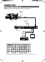
Examples of suitable headsets

JVC 

KA-310

 (Microphone 50 

W

/DC, earphone 150 

W

/1kHz)

Headsets from other manufacturers with:
Microphone output impedance: 50 

W

 to 100 

W

Earphone input impedance: 50 

W

 to 300 

W

The RM-P210 has been set at the factory to be compat-
ible with a dynamic type headset. If it is required to use a
carbon type headset, the setting of the internal circuitry
should be changed; consult your nearest JVC-authorized
service agent. (The modifications and adjustments will
be carried out with charge.)

NOTE

The tally lamp on the camera does not blink or light when
either the camera or the 

RM-P210

 are switched off.

When the CALL button of the camera is pressed, the TALLY
lamp of RM-P210 blinks in red.

NOTE

The RM-P210 has been set at the factory in the “make con-
tact mode”. If it is required to set it to the “voltage supplied
mode”, the setting of the internal circuitry should be
changed; consult your nearest JVC-authorized service
agent. (The modification will then be carried out with charge.)

NOTE

Summary of Contents for RM-P210

Page 1: ...re reference Model No RM P210 Serial No INTRODUCTION CONNECTION PREPARATIONS AND MAIN FUNCTIONS GENERAL CAMERA ADJUSTMENTS MENU OPERATION CALL TALLY INTERCOM LEVEL FULL AUTO F1 SHUTTER GAIN F2 F3 MENU SHUTTER GAIN PAINT AUTO B R W BAL AUTO MANU WHITE MASTER BLACK POWER I O IRIS STEP SHUTTER MENU PUSH ON DOWN UP VARIABLE PUSH ON HIGH LOW B A PRESET CLOSE OPEN MID DOWN UP F4 BARS REMOTE CONTROL UNIT...

Page 2: ...ian to replace your obsolete outlet Do not defeat the safety purpose of the grounding plug 11 For added protection for this product during a lightning storm or when it is left unattended and unused for long periods of time unplug it form the wall outlet and disconnect the antenna or cable system This will prevent damage to the product due to lightning and power line surges 12 Do not allow anything...

Page 3: ...erate the equipment The lightning flash with arrowhead symbol within an equilateral triangle is intended to alert the user to the presence of uninsulated dan gerous voltage within the product s enclosure that may be of sufficient magnitude to consti tute a risk of electric shock to persons The exclamation point within an equilateral tri angle is intended to alert the user to the pres ence of impor...

Page 4: ...era Genlock Function Built In Genlocking is possible using a composite video VBS or a black burst BB signal The SC and H phases can be ad justed from the front panel FEATURES PROVIDED ACCESSORIES AND DOCUMENTS PRECAUTIONS FOR PROPER USE When an intercom is used radio interference may occa sionally affect any system that is connected to the RM P210 In such a case the INTERCOM G GND terminal provide...

Page 5: ...l mode is set which is indi cated by the lighting of the lamp in the AUTO MANU but ton 9 use this knob to adjust the iris aperture between CLOSE and OPEN When the iris mode is AUTO when the lamp in the button is not lit up the auto iris level can be fine adjusted with this knob REF Iris Adjustment on page 17 INTRODUCTION CONTROLS CONNECTORS AND INDICATORS Front panel 4 CALL button with lamp The ca...

Page 6: ...ration or adjust the R gain during manual white balance adjustment B Use this knob to fine adjust the B gain during the white paint operation or adjust the B gain during manual white balance adjustment REF White Balance Adjustment on page 18 SHUTTER control with ON OFF button When this knob is pressed the shutter speed variation func tion is turned alternately ON and OFF When the shutter speed var...

Page 7: ...nal output connectors The settings of the output signals from these connectors can be switched between RGB R Y Y B Y and Y C using the SIG SELECT switch on the camera adapter or by us ing the menu setup of the camera When Y C is selected the Y signal is output from the G connector and the C signal is output from the R connector 7 COMPOSITE VIDEO signal output connectors These terminals output two ...

Page 8: ...UT WHT BAL VTR ON OFF AUTO IRIS LOLUX BACK L NORMAL SPOT L STRETCH NORMAL COMPRESS LIGHT ON OFF COUNTER AUDIO SELECT MANUAL AUTO CH 1 CH 2 CH 1 CH 2 REAR FRONT RM AUDIO INPUT MODE CTL TC UB CH 1 MIX CH 2 RESET OPERATE WARNING MONITOR SELECT CH 1 AUDIO LEVEL CH 2 VTR ON OFF INCOM MIC INCOM MIC LEVEL POWER OFF RM DC IN BATT CALL CARBON DYNAMIC FULL AUTO BLACK RTS Connection of Cameras and Viewfinder...

Page 9: ...GENLOCK INPUT VIDEO OUTPUT Y C OUT CAMERA CABLE R R Y B B Y COMPOSITE VIDEO G Y To power supply GY DV550 SHUTTER STATUS MENU FILTER 3200k 1 5600k 1 8ND 2 5600k 1 64ND 3 ALARM MONITOR OPERATE NG GAIN OUTPUT WHT BAL VTR ON OFF AUTO IRIS LOLUX BACK L NORMAL SPOT L STRETCH NORMAL COMPRESS LIGHT ON OFF COUNTER AUDIO SELECT MANUAL AUTO CH 1 CH 2 CH 1 CH 2 REAR FRONT RM AUDIO INPUT MODE CTL TC UB CH 1 MI...

Page 10: ...AUTO CH 1 CH 2 CH 1 CH 2 REAR FRONT RM AUDIO INPUT MODE CTL TC UB CH 1 MIX CH 2 RESET OPERATE WARNING MONITOR SELECT CH 1 AUDIO LEVEL CH 2 VTR ON OFF INCOM MIC INCOM MIC LEVEL POWER OFF RM DC IN BATT CALL CARBON DYNAMIC FULL AUTO BLACK IRIS switch A or AUTO OPERATE switch ON POWER switch RM MODE switch RM EAR PHONE INCOM LEVEL MIC CAM AD 60dB BETA RGB RM AUDIO LEVEL 20dB Mg VTR MIX SELECT VTR SIG ...

Page 11: ...switches as shown on the previous page 3 Press the POWER switch of the RM P210 to ON CONNECTION TURNING THE POWER ON When an item is controllable from both the RM 210 and the camera the control from the camera is defeated Note that the items that are controllable from the RM 210 are variable depending on the camera models When connecting the RM P210 to the camera do not connect a local remote cont...

Page 12: ...100M 5 After setting the value press the control knob to move the cursor back to 2A LENGTH Fine adjusting theY luminance signal level 6 Turn the control knob to move the cursor to 2B Y CABLE EQ then press the control knob to move the cursor to the currently set value 7 Turn the control knob to fine adjust the Y level variable from 128 to NORMAL and up to 127 8 After setting the value press the con...

Page 13: ...ay 1B SC COARSE 8 Press the control knob to move the cursor to the cur rently set value then turn the control knob to adjust the SC COARSE value to 0 90 180 or 270 9 After the coarse adjustment press the control knob to move the cursor back to 1B SC COARSE then press the control knob to display 1C SC FINE 10 Press the control knob to move the cursor to the cur rently set value then turn the contro...

Page 14: ...t terminals on the rear panel Rear panel Front panel H G C C PVW PGM TALLY INTERCOM AUX VIDEO INPUT G CALL TALLY INTERCOM LEVEL FULL AUTO F1 SHUTTER GAIN F2 BARS RTS INTERCOM LEVEL control 2 CABLE Intercom jack CALL TALLY INTERCOM LEVEL FULL AUTO F1 SHUTTER GAIN F2 BARS CALL button 2 CABLE H G C C PVW PGM TALLY INTERCOM AUX VIDEO INPUT G RTS PGM Program terminal PVW Preview terminal C Common termi...

Page 15: ...witched from ON to OFF and the lamp in the key turns off Checking the assigned functions Press the MENU button to display the functions assigned to the function keys for about 3 seconds in up to 7 characters per function as shown in the figure on the left M FULL AUTO F1 SHUTTER GAIN F2 F3 MENU S MENU DO F4 BARS STR CMP OFF 0dB ALC LUX F1 F2 F3 F4 LCD display 1 M FULL AUTO F1 SHUTTER GAIN F2 F3 MEN...

Page 16: ... ON DOWN UP VARIABLE PUSH ON HIGH LOW MID DOWN UP F4 BARS 1 1000 SHUTTER control SHUTTER lamp SHUTTER GAIN F3 MENU SHUTTER GAIN PAINT AUTO B R W BAL WHITE STEP SHUTTER MENU PUSH ON DOWN UP VARIABLE PUSH ON HIGH LOW B A PRESET MID DOWN UP F4 9dB GAIN display GAIN control GAIN lamp GAIN STEP switch 2 When the GAIN control is pressed the VARIABLE mode starts and the GAIN lamp lights up 3 The gain can...

Page 17: ...the IRIS con trol 2 When the lamp in the IRIS AUTO MANU button is lit by pressing the button the iris control is set to MANUAL mode in which the iris level can be controlled using the IRIS control W T Iris MODE switch PAINT AUTO B R W BAL AUTO MANU WHITE MASTER BLACK POWER I O IRIS P B A PRESET CLOSE OPEN MID REMOTE CONTROL UNIT RM P210 IRIS AUTO MANU button IRIS control When ALC EEI or FULL AUTO ...

Page 18: ...n control IRIS AUTO MANU button AUTO WHITE button W BAL switch PAINT button The lamp in the button lights up during an auto white balance adjustment or an auto setup of the camera and turns off when it completes The lamp in the button also lights up when the FAW Full Auto White balance adjust function of the cam era is working The LCD display shows the operating status of the auto white balance ad...

Page 19: ... 4M ASPECT RATIO 4 3 16 9 LETTER 4N DNR OFF ON 4O DNR LEVEL LOW MIDDLE HIGH AUTO 4Z BACK 5Z BACK 6 LCD MODE 8 EXIT 6A CONTRAST 6B BACKLIGHT 6Z BACK 5 to NORMAL to 5 OFF ON 5 OPERATION Netted items are saved in the scene file 5A SHUTTER 5C V GAIN MAX 5D GAIN LOW STEP VARIABLE 9 0 dB 12 0 dB 18 0 dB 5B V GAIN STEP 0 1 dB 1 0 dB 3 dB 0 dB 3 dB 6 dB 9 dB 12 dB 18 dB 5E GAIN MID 3 dB 0 dB 3 dB 6 dB 9 d...

Page 20: ... control knob to move the cursor to the de sired item 1 1 GEN LOCK 2 CABLE Cursor 2 1 GENLOCK 2 CABLE 2A LENGTH 20M 3 Item Setting 4 2A LENGTH 20M 5 2A LENGTH 100M 3 Press the control knob to display the name and current setting of the next item 4 Press the control knob to move the cursor to the posi tion of the currently set value 5 Turn the control knob to adjust the setting 6 2A LENGTH 100M 6 P...

Page 21: ... cannot be adjusted with SC FINE restart the adjustment from SC COARSE Return to the previous display 0 to 255 0 90 180 270 0 to 255 CABLE MENU This menu sets the camera cable length according to the actual length used REF Camera Cable Length Setup on page 12 20M NORMAL NORMAL No Item Function Operation Available Settings Initial Setting 2A 2B 2C 2Z LENGTH Y CABLE EQ C CABLE EQ BACK Set according ...

Page 22: ...ss the control knob to move the cursor to the 3B WRITE FILE 7 WRITE FILE B CANCEL B 8 WRITE FILE B OK B 9 STR CMP OFF 0dB ALC LUX 5 Press the control knob again to move the cursor to the position indicating A 6 To write data in file B turn the control knob to move the cursor to file B 7 If the control knob is pressed now the LCD display shows WRITE FILE B and the cursor moves to CANCEL If it is no...

Page 23: ...ich displays natural wet skin colors by reducing detail enhancement on the skin areas OFF Skin tone detail function is deactivated ON Skin tone detail function is activated ON OFF setting whether the auto knee function is activated accord ing to the knee point setting to be made below OFF Auto knee function is deactivated ON Auto knee function is activated Sets the knee point level at which the au...

Page 24: ...hes the signals of the dark areas in the im age to enhance them and clarify the difference between the bright and dark areas COMPRESS When the captured image is bright in overall and has few contrast the gain of the dark areas is compressed to provide contrast Sets the picture size of the video signal 4 3 4 3 screen output 16 9 16 9 screen output LETTER Letter size 16 9 screen output ON OFF settin...

Page 25: ... to 12 0 dB 18 0 dB The GAIN control can vary the gain up to 18 0 dB Selects the gain value when the front panel GAIN switch is set to the LOW position Selects the gain value when the front panel GAIN switch is set to the MID position Selection of the gain value when the front panel GAIN switch is set to the HIGH position ON OFF setting of the smooth transition function which prevents sudden chang...

Page 26: ... Available Settings Initial Setting 6A 6B 6Z CONTRAST BACKLIGHT BACK Adjusts the contrast of the LCD display Adjusts the setting of the backlight of the LCD display OFF Backlight is turned off ON Backlight is turned on Returns to the previous display 5 to NORMAL to 5 OFF ON MENU OPERATION ...

Page 27: ...ges 21 to 27 Other status settings are reset as shown below 2 Press the control knob to display 7A SYSTEM RESET 3 Press the control knob to move the cursor to CAN CEL If you do not want to reset the values you have set press the control knob now 4 If you want to reset the values turn the control knob to move the cursor to OK 5 Press the control knob to reset the values you have set to the initial ...

Page 28: ... Cause Check Point ERROR MESSAGES When the LCD display shows one of the following error messages during an auto white balance adjustment and AUTO SET mode check Cause and Check Point below and then retry the auto white balance adjustment The error message is displayed for about 5 seconds Displayed Message AUTO WHITE A B ERROR LOW LIGHT AUTO WHITE A B NG OBJECT AUTO WHITE A B ERROR OVER LIGHT AUTO ...

Page 29: ...IS AUTO IRIS AI LEVEL MANUAL IRIS IRIS LEVEL MASTER BLACK WHITE PRESET MANUAL BALANCE BALANCE Rch BALANCE Bch AUTO A 1 AUTO B 2 PAINT Rch PAINT Bch FAW AUTO SET WHITE GAIN 3 dB 0 dB 3 dB 6 dB 9 dB 12 dB 18 dB ALC EEI VARIABLE GAIN LOLUX OFF ON SHUTTER OFF 1 100 1 250 1 500 1 1000 1 2000 VARIABLE TALLY PREVIEW CALL BARS OFF ON DETAIL OFF CONTOUR ON DETAIL LEVEL DETAIL V H BAL DETAIL FREQUENCY LOW M...

Page 30: ...of the camera system The RM P210 has been set at the factory in the make contact mode If it is required to set it to the voltage supplied mode the setting of the internal circuitry should be changed consult your nearest JVC authorized service agent The modification will then be carried out with charge P 14 White balance adjustment cannot be started Is the W BAL switch set to A or B Is FAS or FAW O...

Page 31: ...20 W unbalanced RTS The RTS ter minals are not designed to ac cept a power supply Tally Contact supply General Input voltage 120 V AC 60 Hz Power consumption 75 W KY D29W VF P550W Mass 5 2 kg Operating temperatures 5 C to 45 C Accessory Power cord 2 m x 1 Instructions x 1 External Dimensions Unit mm Design and specifications are subject to change without notice 54 44 32 483 465 370 306 283 209 272...

Page 32: ...mark owned by Victor Company of Japan Limited is a registered trademark in Japan the U S A the U K and many other countries 2005 Victor Company of Japan Limited RM P210 REMOTE CONTROL UNIT Printed in Thailand SC961002 003 H ...

Reviews: