


4
Do not supply power to the RTS terminals at the rear. These
terminals are not designed to accept a power supply.
To prolong the service life of the
RM-P210
, do not use it or
store it in the following places.
A place subject to extremely high or low temperatures.
A place subject to excessive vibration.
A place subject to excessive dust.
A place subject to high humidity.
A place near to a strong source of noise.
Do not apply strong vibrations or impact to the
RM-P210
during installation or transportation.
If the supply voltage is too high or low, the service life of the
RM-P210
may be reduced or it may not be able to provide
an optimum performance.
Do not connect or disconnect the camera cable connector
while the
RM-P210
is ON.
After turning the RM-210 OFF, wait at
least 10 seconds
before turning it ON again.
Noise may interfere with the video when the RM-210 is in-
stalled near a source of strong magnetism, such as a radio
or TV transmitting antenna, power transformer or motor.
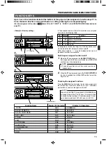
While the values set by using the menus are retained in the
memory even after the unit is turned off, those set using the
front panel switches and controls are retained for about 10
days only and then the factory-set defaults are reset.
As the LCD contrast is reduced at low temperatures, it should
be re-adjusted before use in such conditions.
REF.
: Item “6A: CONTRAST” on page 26.
When a transceiver or cellular phone is used near to a RM-
210 or to a camera connected to it, noise may interfere with
the video. However, this is not a malfunction.
INTRODUCTION
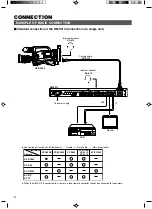
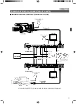
Cable extension up to 100 meters
The cable between the camera and the RM-P210 Remote
Control Unit can be extended up to 100 meters using the
optional VC-P110 series camera cables. Even when the
cable is extended, the power to the camera is supplied from
the RM-P210 so there is no need to provide a separate
power supply for the camera.
Genlock Function Built In
Genlocking is possible using a composite video (VBS) or a
black burst (BB) signal. The SC and H phases can be ad-
justed from the front panel.
FEATURES
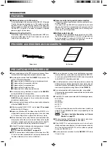
PROVIDED ACCESSORIES AND DOCUMENTS
PRECAUTIONS FOR PROPER USE
When an intercom is used, radio interference may occa-
sionally affect any system that is connected to the RM-P210.
In such a case the INTERCOM G (GND) terminal provided
to the RM-P210 should be grounded.
In a multiple camera setup, if the adjustments made to the
different cameras deviate significantly, the cameras may not
be able to function satisfactorily. Be sure to adjust the cam-
eras accordingly before using them with the
RM-P210
.
Use camera cables with standard lengths, as specified.
Otherwise, the camera cable compensation may not be able
to work efficiently.
The RM-P210 can be connected with the following cameras:
●
GY-DV550
●
KY-D29
●
KY-D29W
●
KY-27C
●
KY-19
For the viewfinder to be used with each camera model, see
page 8. The controllable functions vary depending on the
camera model.
REF.
: "Functions Available Depending on Camera
Models" on page 29.
When connecting the RM-P210 to the camera, do not con-
nect
a local remote controller
to the camera.
If the RM-P210 is rack-mounted, be sure to insert venti-
lated panels above and below it in order to improve ventila-
tion. Do not stack two RM-P210 units or place any object
on top of a RM-P210 unit.
To save power consumption, turn the
RM-P210
OFF when
it is not in use.
Power cord
Instructions
CAMERA CONTROL UNIT
RM-P210
INSTRUCTIONS
R
Camera control using serial communication
The camera control signals are sent by the serial data trans-
mission method.
The camera and the RM-P210 are connected by two data
lines so that the CPUs incorporated in the camera and the
RM-P210 are in intercommunication, thus facilitating accu-
rate camera control operations.
Multiple output circuits
In addition to two composite video output circuits (VBS),
the R/G/B component signals, Y/R-Y/B-Y component sig-
nals or separate Y/C signals (for S-VHS VCR) can be se-
lected according to the purpose or application.