


22
Drive Units
7-3. Setting the SCSI ID numbers, etc.
1.
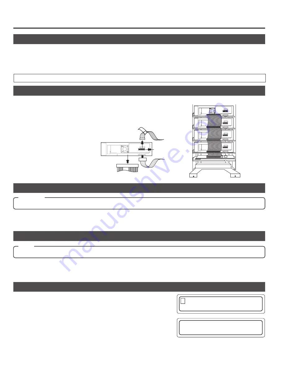
Connect the control cable (14P).
• Connect the cable with the corresponding number to the drive bay No. If the
cable with the wrong number is connected, it will lead to the equipment mal-
functioning.
s
Procedure for the setting the SCSI ID Nos. and other jumpers, please refer to the specified section(s) of the corresponding
drive instruction manuals.
s
Make sure to turn the power OFF before starting with the setting procedure. If the procedure is carried out with the power
ON, it will cause malfunction.
s
The new ID Nos. will become effective from the moment the power is turned on.
7-4. Connecting the cables
7-5. Installing the panels
1.
Attach rear and side panels.
• Screw the panels on, following the procedure in "7-1
Removing the panel" on page 21 in the reverse order.
Power cable
Control cable
Drive jumber settings
SCSI cable
14p
1
4p
2
3
1
Internal SCSI cable(approx. 1.2 m)
Changer SCSI
board
Drive No. 4
4
Drive No. 3
3
Drive No. 2
2
Drive No. 1
1
CAUTION
s
Check the installation screws and cables before installing the panel. Insufficient connections may cause malfunctions.
Please refer to a relevant section of an optional drive unit's instruction manual for
the correct connector positions of the cables.
7-6. Automatic drive detection mode
1.
While holding key "8" on the control panel, turn on the
MC-8100U.
Note:
After installing, adding, exchanging or removing drives, be sure to execute the auto drive detection mode to prevent any malfunction.
s
The new SCSI ID Nos. should not conflict with the ID Nos. of other SCSI equipment on the same SCSI bus.
2.
Connect the power cable (4P).(The fig-
ure shows the case with the MC-R200U.)
3.
Connect the SCSI cable
7-7. Drive type display
1.
Press the MODE key while the LCD display is in normal display mode
(to display Menu display).
2.
Press the SELECT key 8 times (to display "9. DRIVE DISPLAY").
3.
Press the ENTER key (to select "9. DRIVE DISPLAY").
4.
The type of the drive in each drive bay will be displayed. (Each press of
the SELECT key displays the information on the next drive.)
The types of the installed drives can be confirmed by the display.
2.
Close the door
(
a
See "5. Door Opening/Closing" on page 17.)
2.
When the LCD display shows "DRIVE DETECTION
COMPLETED", turn off the power of the MC-8100U.
3.
Turn the MC-8100U on again.
9 . D R I V E
D I S P L A Y
1 . N O R M A L
D I S P L A Y
D R 1 : D V D – R A M
D R 2 : R O M /
e t c
R
Meaning of the display
"DVD-RAM"
: DVD-RAM drive
"ROM/R etc"
:Non DVD-RAM drive (CD-ROM/R, DVD-ROM, etc.)
"NO DRIVE"
: Drive is not connected or installed
"UNKNOWN"
: When drive detection mode has not been executed.
●
If the automatic drive detection mode has not been executed, the LCD displays “UNKNOWN DRIVE DETECTED”.
Summary of Contents for MC-8100U
Page 63: ...1C 3 4 CHASSIS SCHEMATIC DIAGRAM 3 4 MC 8100U ...
Page 64: ...2C 両面 3 5 3 5 3 5 3 5 CHASSIS CIRCUIT BOARD MC 8100U MC 8100U ...
Page 65: ...1C 3 6 3 6 3 6 SCSI SCHEMATIC DIAGRAM MAGAZINE1 MAGAZINE2 MC 8100U MC 8100U ...
Page 66: ...2C 両面 3 7 3 7 3 7 3 7 SCSI CIRCUIT BOARD MC 8100U MC 8100U ...
Page 69: ...1C 3 10 MAIL SLOT SCHEMATIC DIAGRAM 3 10 3 10 MAIL SLOT MOTOR MECHA SW MC 8100U MC 8100U ...
Page 70: ...3 11 MAIL SLOT CIRCUIT BOARD 3 11 MAIL SLOT SENSOR POSI IN MC 8100U ...
Page 71: ...3 12 S MOT SCHEMATIC DIAGRAM 3 12 MC 8100U ...
Page 72: ...3 13 3 13 S MOT CIRCUIT BOARD MC 8100U ...
Page 73: ...3 14 3 14 DISPLAY SCHEMATIC DIAGRAM MC 8100U ...