1-20 (No.MA387<Rev.003>)
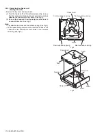
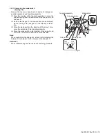
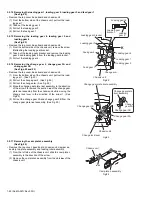
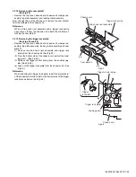
3.2.12 Removing the select arm R and select lock arm
(See Figs.17 and 18)
• Remove the top cover, base board, chassis unit, clamper as-
sembly, trigger arm and top plate assembly.
(1) From the top side of the top plate assembly, remove the
link gear spring from the sections
ad
of the link gear L and
link gear R. (See Fig.17.)
(2) Remove the link gear R in an upward direction while releas-
ing the claws
ae
of the link gear R in the direction of the ar-
row. (See Fig.17.)
(3) Move the select arm R in the direction of the arrow 1 to re-
move the sections
af
of the top plate assembly. (See
Fig.17.)
(4) Move the select arm R in the direction of the arrow 2 and
remove the select arm R from the sections
ag
. (See
Fig.17.)
(5) From the bottom side of the top plate assembly, remove
the select lock arm spring from the section
ah
. (See
Fig.18.)
(6) From the top side of the top plate assembly, remove the
section
aj
of the select lock arm from the top plate assem-
bly at first and remove the sections (
ak
,
am
) of the select
lock arm from the top plate assembly. (See Fig.18.)
Note:
• When removing the select lock arm spring, be careful not to
lose it. (See Fig 18.)
• When reattaching the link gear R, attach it after aligning the
hole
an
of the link gear R to the hole
an
of the link gear L.
(See Fig.17.)
Reference:
When reassembling, reverse the above removing procedure.
Fig.17
Fig.18
1
2
Link gear L
Link gear R
Top plate assembly
Link gear spring
ad
ae
ae
an
an
Link
gear R
Link
gear L
ag
af
Select arm R
aj
ak
Select lock arm
Top plate assembly
am
ah
Select lock
arm spring
Summary of Contents for KD-BT11E
Page 29: ... No MA387 Rev 003 1 29 ...
Page 66: ... M E M O ...

