(No.MA387<Rev.003>)1-13
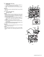
3.2.2
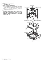
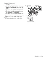
Removing the push switch
(See Figs.3)
(1) From the bottom side of the CD mechanism assembly, re-
move the screw
B
attaching the push switch.
(2) Take out the push switch from the CD mechanism assem-
bly.
Reference:
Remove the wires from soldered sections
b
of the push switch
as required.
3.2.3
Removing the base board
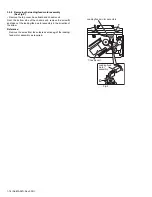
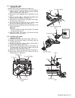
(See Figs.3 and 4)
Caution:
Solder the short land
c
before the flexible wire is disconnected
from the connector on the pickup. If the flexible wire is discon-
nected without applying solder, the pickup may be destroyed
by static electricity. (See Fig.3.)
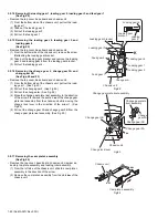
(1) From the bottom side of the CD mechanism assembly, re-
move the screw
C
attaching the base board. (See Figs.3
and 4.)
(2) Solder the short land c on the pickup. (See Fig.3.)
(3) Disconnect the flexible wire from the connector on the pick-
up. (See Fig.3.)
(4) Remove the base board from the joints
d
of the frame in the
direction of the arrow. (See Figs.3 and 4.)
Reference:
Remove the wires from the soldered sections
e
on the base
board as required. (See Fig.3.)
Caution:
When reattaching the base board, be sure to remove solder
from the short land c after connecting the flexible wire. (See
Fig.3.)
Fig.3
Fig.4
B
b
Wires
Push switch
Pickup
e
C
Base board
d
Pickup
c
Connector
Flexible wire
Frame
CD mechanism
assembly
C
Base board
Flexible wire
Frame
d
Summary of Contents for KD-BT11E
Page 29: ... No MA387 Rev 003 1 29 ...
Page 66: ... M E M O ...

