


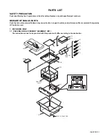


(No.82933)1-27
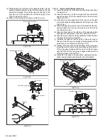
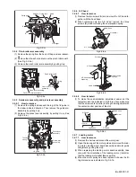
3.2.21 Tension brake assembly, reel disk (supply side) and
tension arm assembly
3.2.21.1 How to remove
(1) Remove the three lugs of the tension brake assembly from
the main deck and pull them off.
(2) Remove the reel disk (supply side) by loosening in the ar-
row-indicated direction the main brake assembly (supply
side).
(3) Remove the tension spring on the back of the main deck.
Then release the lug of the tension arm bearing in the ar-
row-indicated direction and draw out the tension arm as-
sembly. (See Fig. 3-2-21a.)
Fig.3-2-21a
3.2.22 Idler lever, idler arm assembly
3.2.22.1 How to remove
(1) Remove the lug of the idler lever from the main deck and
remove the hook fitted in the idler arm assembly hole by lift-
ing it.
(2) Remove the slit washer and pull out the idler arm assem-
bly.
Fig.3-2-22a
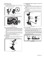
3.2.23 Stator assembly
(1) Remove the flat cable.
(2) Remove the two screws (A), (B) and remove the lug wire.
(3) Remove the stator assembly by lifting in the arrow-indicat-
ed direction. (Take care that the brush spring does not
jump out.)
Notes:
•
Be careful not to lose the brush and spring.
•
There are some models that do not use the lug wire.
Refer to the parts list for these models.
•
When tightening the screw (B), place the caulked part of
the lug terminal near to the shaft of the drum and then
tighten it.
•
After installation, be sure to perform the switching point
adjustment according to the electrical adjustment pro-
cedure.
Fig.3-2-23a
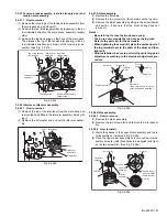
3.2.24 Rotor assembly
3.2.24.1 How to remove
(1) Remove the stator assembly.
(2) Remove the two screws (B) and remove the rotor assem-
bly.
3.2.24.2 How to install
(1) Match the phases of the upper drum assembly and the ro-
tor assembly as indicated in Fig.3-2-24a.
(2) Place the upper drum assembly hole (a) over the rotor as-
sembly holes (b) (with three holes to be aligned) and tight-
en the two screws (B). (See Fig.3-2-24a.)
Fig.3-2-24a
Lugs
Tension brake
assembly
Lug of the tension
arm bearing
Reel disk
(supply side)
Tension arm
assembly
Tension spring
Main brake assembly
(supply side)
Lug
Idler lever
Hook
Idler arm
assembly
Slit washer
Stator assembly
Flat cable
(Take care not to mix up the
polar faces when installing.)
Lug wire
(Note)
Screw (A)
Screw (A)
Lug wire
Drum
shaft
Screw (B)
Screws (B)
Rotor
assembly
Hole(a)
Hole(b)
Screw holes
Upper drum
assembly
The hole is not in
line but is offset
toward the right.
Compress
Spring
CONTACT