


1-32 (No.82933)
4.2 Servo circuit
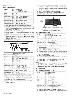
4.2.1
Switching point
(1) Play back the signal (A1) of the alignment tape (A2).
(2) Apply the external trigger signal to D.FF (E) to observe the
VIDEO OUT waveform and V.PB FM waveform at the mea-
suring points (D1) and (D2).
(3) Set the VCR to the manual tracking mode.
(4) Adjust tracking so that the V.PB FM waveform becomes
maximum.
(5) Transmit the code (F1) from the Jig RCU to adjust so that
the trigger point of the VIDEO OUT waveform is changed
from the trailing edge of the V.sync signal becomes the
specified value (G).
(6) Set the VCR to the stop mode.
Fig.4-2-1a Switching point
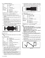
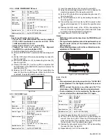
4.2.2
D-VHS switching point
(1) Play back the signal (A1) of the alignment tape (A2).
(2) Apply the external trigger signal to D.FF (E) to observe the
D-VHS envelope waveform at the measuring point (D).
(3) Set the VCR to the manual tracking mode.
(4) Adjust tracking so that the D-VHS envelope waveform be-
comes maximum.
(5) Transmit the code (F) from the Jig RCU to adjust so that the
duration “a” from the waveform end (Hi/Low switching point
of D.FF) to the rising edge of subcode area becomes the
specified value (G).
(6) Set the VCR to the stop mode or eject mode.
(7) Play back the signal (A1) of the alignment tape (A3).
(8) Repeat steps (2) to (6) in the mode (B3).
Fig.4-2-2a D-VHS switching point
4.2.3
Slow tracking preset
(1) Record the signal (A2) in the mode (B1), and play back the
recorded signal.
(2) Set the VCR to the manual tracking mode.
(3) Set the VCR to the FWD slow (+1/6x) mode.
(4) Transmit the code (F) from the Jig RCU to adjust so that the
noise bar becomes the specified value (G) on the TV mon-
itor in the slow mode.
(5) Set the VCR to the Stop mode.
(6) Confirm that the noise bar is (G) on the TV monitor in the
slow mode.
(7) Repeat steps (3) to (6) in the REV slow (–1/6x) mode.
(8) Repeat steps (1) to (7) in the mode (B2).
Note:
•
For FWD slow (+1/6x) playback, transmit the code “08”
from the Jig RCU to enter the slow playback mode, and
transmit the code “D0” for REV slow (–1/6x) mode.
4.3 Video circuit
4.3.1
SD EE COMPONENT Y level
(1) Insert the cassette tape (A2) to enter the mode (B).
(2) Observe the Y OUT waveform at the measuring point (D).
Signal
(A1)
(A2)
• Stairstep signal
Alignment tape
(SP, stairstep, NTSC) [MHP]
Mode
(B)
• PB
Equipment
(C)
• Oscilloscope
Measuring point (D1)
(D2)
• TP501 (Y TO SE) [Main board]
• TP106 (PB-FM) [Main board]
External trigger (E)
• TP111 (D.FF)/slope : –
Adjustment part (F1) • Jig RCU: Code “51” or “52”
Specified value (G)
• 7.5 ± 0.5H
Adjustment tool (H)
• Jig RCU [PTU94023B]
Signal
(A1)
(A2)
(A3)
• Color (colour) bar
• (STD) Alignment tape [MD-1]
• (HS) Alignment tape [MD-1H]
Mode
(B1)
(B2)
(B3)
• PB
• D-VHS STD
• D-VHS HS
Equipment
(C)
• Oscilloscope
Measuring point (D)
• (STD) TP621 (PB DATA1)
• (HS) TP622 (PB DATA2)
External trigger (E)
• (STD) TP111 (VIDEO/STD/HS1 FF)
• (HS) TP602 (A/HS2 FF)
Adjustment part (F)
• Jig RCU: Code “51” or “52”
Specified value (G)
• 230 ± 20µsec
Adjustment tool (H)
• Jig RCU [PTU94023B]
V.sync
Trigger point
Switching point
V. rate
Signal
(A1)
(A2)
• Ext. input
• Color (colour) bar signal [NTSC]
Mode
(B1)
(B2)
• VHS SP
• VHS EP
Measuring point (D)
• TV-Monitor
Adjustment part (F)
• Jig code “71“ or “72”
Specified value (G)
• Minimum noise
Adjustment tool (H)
• Jig RCU [PTU94023B]
Signal
(A1)
(A2)
• Internal color bar
• S-VHS
Mode
(B)
• EE
Equipment
(C)
• Oscilloscope
Measuring point (D)
• COMPONENT Y terminal
EVR mode
EVR address
(F1)
(F2)
(F3)
(F4)
(F5)
• Jig code “95”
• "01 : **"
• Jig code “21”
• Jig code “18” or “19” (C/-)
• Jig code “3C”
Specified value (G)
• 1.00 ± 0.02 Vp-p (terminated)
Adjustment tool (H)
• Jig RCU [PTU94023B]
Sub code area
D-VHS
envelope
End of waveform (D.FF signal Hi/Low switching point)
a


