


1-16 (No.82933)
3.1.4.2
In case of mechanical failure
If you cannot remove the cassette tape which is loaded because
of any mechanical failure, manually remove it by taking the fol-
lowing steps.
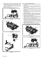
(1) Unplug the power cable and remove the top cover, front
panel assembly and others so that the mechanism assem-
bly is visible. (See SECTION 1 DISASSEMBLY.)
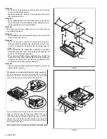
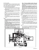
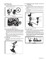
(2) While keeping the tension arm assembly of the mechanism
assembly free from tension, pull the tape on the pole base
assembly (supply or take-up side) out of the guide roller.
(See Fig.3-1-4c.)
(3) Take the spring of the pinch roller arm assembly off the
hook of the press lever assembly, and detach it from the
tape. (See Fig.3-1-4d.)
(4) In the same way as in the electrical failure instructions in
2.1.3-1(5), remove the top guide.
(5) Raise the cassette tape cover. By keeping it in that posi-
tion, draw out the cassette tape case from the cassette
holder and take out the tape.
(6) By hanging the pinch roller arm assembly spring back on
the hook, take up the slack of the tape into the cassette.
Fig.3-1-4c
Fig.3-1-4d
3.1.5
Maintenance and inspection
3.1.5.1
Cleaning
Regular cleaning of the transport system parts is desirable but
practically impossible. So make it a rule to carry out cleaning of
the tape transport system whenever the machine is serviced.
When the video head, tape guide and/or brush get soiled, the
playback picture may appear inferior or at worst disappear, re-
sulting in possible tape damage.
Note:
•
Absolutely avoid sweeping the upper drum vertically as
this will cause damage to the video head.
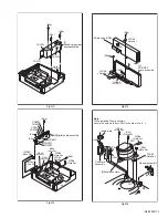
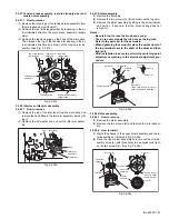
(1) When cleaning the upper drum (especially the video head),
soak a piece of closely woven cloth or Kimu-wipe with alco-
hol and while holding the cloth onto the upper drum by the
fingers, turn the upper drum counterclockwise.
(2) To clean the parts of the tape transport system other than
the upper drum, use a piece of closely woven cloth or a cot-
ton swab soaked with alcohol.
(3) After cleaning, make sure that the cleaned parts are com-
pletely dry before using the video tape.
3.1.5.2
Lubrication
With no need for periodical lubrication, you have only to lubricate
new parts after replacement. If any oil or grease on contact parts
is soiled, wipe it off and newly lubricate the parts.
Note:
•
See the “mechanism assembly” diagram of the parts list
for the lubricating or greasing spots, and for the types
of oil or grease to be used.
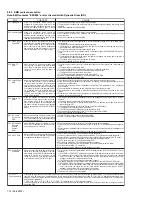
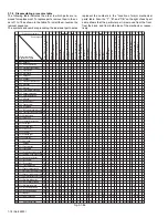
3.1.6
Suggested servicing schedule for main components
The following table indicates the suggested period for such ser-
vice measures as cleaning,lubrication and replacement.
In practice, the indicated periods will vary widely according to en-
vironmental and usage conditions.However, the indicated com-
ponents should be inspected when a set is brought for service
and the maintenance work performed if necessary. Also note that
rubber parts may deform in time,even if
the set is not used.
C : Cleaning
X : Inspection or Replacement if necessary
Pole base assembly (take-up side)
Pole base assembly
(supply side)
Tension arm assembly
Guide pole guard
Pinch roller arm assembly
Press lever assembly
Take the spring
off the hook, and
detach it from the
tape.
System
Parts name
Operation hours
1000H
2000H
Tape
transport
Drum assembly
C,X
X
A/C head
C,X
C,X
Pinch roller arm assembly
C
C
Full erase head
C
C
Tension arm assembly
C
C
Capstan motor (Shaft)
C
C
Guide arm assembly
C
C
Drive
Capstan motor
X
Capstan brake assembly
X
Main brake assembly
X
Belt (Capstan)
X
X
Loading motor
X
Clutch unit
X
Worm gear
X
Control plate
X
Other
Rotary encoder
X


