


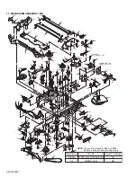


(No.82933)1-35
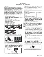
4.5.2 HD EE COMPONENT CB level
Notes:
How to input the HD color bar signal.
•
Connect an i.LINK cable between the another playback
VCR's i.LINK input/output connector and this VCR's
i.LINK input/output connector.
•
Select input location"I-1 etc." on this VCR.
•
Playback the color bar portion of the alignment
tape[MD-1H] on another playback VCR.
(1) Input the signal (A2) to enter the mode (B).
(2) Observe the PB/CB OUT waveform at the measuring point
(D).
(3) Set the VCR to the EVR mode by transmitting the code (F1)
from the Jig RCU.
(4) Set the EVR address to (F2) by transmitting the code (F3)
from the Jig RCU.
(5) Transmit the code (F4) from the Jig RCU to adjust so that
the PB/CB level of the PB/CB OUT waveform becomes the
specified value (G).
(6) Release the EVR mode of the VCR by transmitting the
code (F5) from the Jig RCU again. (When the EVR mode
is released, the adjusted data is memorized.)
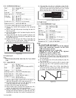
Fig.4-3-2a
4.5.3 D-VHS REC level
(1) Insert the cassette tape (A3) to enter the mode (B1).
(2) Apply the external trigger signal to D.FF (E) to observe the
waveform appeared at the measuring point (D).
(3) Set the VCR to the EVR mode by transmitting the code (F1)
from the Jig RCU.
(4) Set the EVR address to (F2) by transmitting the code (F3)
from the Jig RCU.
(5) Transmit the code (F4) from the Jig RCU to adjust so that
the waveform signal level “a” becomes the specified value
(G).
(6) Release the EVR mode of the VCR by transmitting the
code (F1) from the Jig RCU again. (When the EVR mode
is released, the adjusted data is memorized.)
(7) Repeat steps (2) to (6) in the mode (B2).
Notes:
•
GND (Ground) should be taken from the PRE/REC board
shield case.
•
The signal level adjustment should be performed by set-
ting the center (centre) of the darkened section on the
CRT bright line.
•
After adjusting, always perform the confirmation and re-
adjustment of the item 4.5.4.
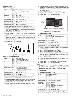
Fig.4-5-1a D-VHS REC level
4.5.4 PLL f0
Notes:
•
This adjustment should be done after the “D-VHS REC
level adjustment” for the Digital circuit has been com-
pleted.
•
Do not connect the probe or any other jig to the TP or
shield case of the PRE/REC board during adjustment.
•
If auto adjustment is not completed by the above pro-
cedure, re-adjust the adjustment item 4.5.3 again.
(1) Insert the cassette tape (A3) to enter the mode (B1).
(2) Set the VCR to the Auto adjust mode by transmitting the
code (F1) from the Jig RCU. When the VCR enters the stop
mode, the adjustment is completed. When the VCR enters
the eject mode, insert the cassette tape again.
(3) Release the Auto adjust mode of the VCR by transmitting
the code (F2) from the Jig RCU.
(4) Repeat steps (2) to (3) in the mode (B2).
Signal
(A1)
(A2)
• Ext. input (i. LINK)
• HD color bar signal
Mode
(B)
• EE
Equipment
(C)
• Oscilloscope
Measuring point (D)
• COMPONENT PB/CB terminal
EVR mode
EVR address
(F1)
(F2)
(F3)
(F4)
(F5)
• Jig code “95”
• "08 : **"
• Jig code “28”
• Jig code “18” or “19” (C/-)
• Jig code “3C”
Specified value (G)
• 0.525 ± 0.020 Vp-p (terminated)
Adjustment tool (H)
• Jig RCU [PTU94023B]
Signal
(A1)
(A2)
(A3)
• Ext. input
• Optional
• DF-300
Mode
(B1)
(B2)
• D-VHS STD REC
• D-VHS HS REC
Equipment
(C)
• Oscilloscope
Measuring point (D)
• (STD) TP611 (REC LEVEL1)
• (HS) TP612 (REC LEVEL2)
External trigger (E)
• (STD) TP111 (VIDEO/STD/HS1 FF)
[Main board]
• (HS) TP602 (A/HS2 FF)
Adjustment part (F1)
(F2)
(F3)
(F4)
• Jig code “57”
• (STD) A:8
• (HS) A:9
• (STD) Jig code “28”
• (HS) Jig code “29”
• Jig code “18” or “19” (C/-)
Specified value (G)
• 120±5mVp-p
Adjustment tool (H)
• Jig RCU [PTU94023B]
PB/CB level
Signal
(A1)
(A2)
(A3)
• Ext. input
• Optional
• DF-300
Mode
(B1)
(B2)
• D-VHS STD
• D-VHS HS
Adjustment part (F1)
(F2)
• (STD) Jig code “96”
• (HS) Jig code “91”
• Jig code “9B”
Specified value (G)
• STOP mode
Adjustment tool (H)
• Jig RCU [PTU94023B]
a


