EN
81
Master Page: Right
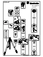
Controls
a
•Menu Wheel [MENU] ........................
•Speaker/Headphone Volume Control
[, –] .................................
b
Snapshot Button [SNAPSHOT].......
c
Power Zoom Lever [T/W] ....................
d
•Exposure Adjustment Button
[EXPOSURE]......................................
•Blank Search Button
[BLANK SEARCH] .............................
e
Dioptre Adjustment Control ................
f
Recording Start/Stop Button ................
g
Power Switch [
A
,
M
, PLAY, OFF] ........
h
Lock Button .........................................
i
•Stop Button [
8
] .................................
•Program AE Button [PROG.AE] .........
j
•Rewind Button [
3
]..........................
•NIGHT Button...................................
k
Play/Pause Button [
4
/
9
] ....................
l
•Fast-Forward Button [
5
] .................
•Wipe or Fader Effect Button
[FADE/WIPE].....................................
m
Index Button [INDEX]..........................
n
Thumbnail Storing Button
[NAVI STORE]......................................
o
•D.S.C. Playback Select Button
[SELECT]....................................
•Navigation Button [NAVI] .................
p
VIDEO/MEMORY Switch
[VIDEO/MEMORY]..............................
q
Title Button [TITLE]..............................
r
•Information Button [INFO]................
•E-Mail Clip Recording Button
[E-MAIL]............................................
s
Battery Release Switch
[BATT.RELEASE] ...................................
t
Cassette Open/Eject Switch
[OPEN/EJECT]......................................
u
Manual Focus Ring...............................
v
Backlight Compensation Button
[BACK LIGHT] .....................................
w
Manual Focus Button [FOCUS]............
x
Monitor Opening Button
[PUSH OPEN]......................................
Connectors
The connectors are located beneath the covers.
Y
S-Video Input/Output Connector
[S-VIDEO]................................
Z
Edit Connector [EDIT] ........................
a
Microphone connector [MIC]
Attach the optional microphone.
b
Headphone Connector [
] .................
No sound is output from the speaker when
headphones are connected to this connector.
c
Digital Video Connector
[DV IN/OUT] (i.Link*)..............
* i.Link refers to the IEEE1394-1995 industry
specification and extensions thereof. The logo
is used for products compliant with the i.Link
standard.
d
USB (Universal Serial Bus)
Connector ............................................
e
DC Input Connector [DC] ..............
f
Audio/Video Input/Output Connector
[AV]..........................................
Indicators
K
Power Lamp....................................
L
Tally Lamp ......................................
Other Parts
j
Shoulder Strap Eyelet .............................
k
Battery Pack Mount ..............................
l
Grip Strap.............................................
m
LCD Monitor ..................................
n
Speaker ................................................
o
Stud Hole
p
Tripod Mounting Socket .......................
q
Card Cover [MEMORY CARD] ............
r
Cassette Holder Cover..........................
s
Lens Hood ..............................................
t
Flash.....................................................
u
Stereo Microphone...............................
v
Info-Shoe
Attach only the optional JVC VL-V3U Video
Light, VL-F3U Flash, MZ-V3U Stereo Zoom
Microphone or MZ-V5U Stereo Microphone.
Make sure to turn off the power of the camcorder
and the video light, flash or microphone before
attaching and removing them.
w
Viewfinder............................................
x
Remote Sensor .....................................
y
Camera Sensor
Be careful not to cover this area, a sensor
necessary for shooting is built-in here.
z
INFO LCD ......................................
GR-DV4000PAL.book Page 81 Friday, February 14, 2003 10:30 PM